


")

Most designs of these antennas described in the literature [1, 2], and that, due to their simplicity they are used by many Amateurs. Well-known and their main drawbacks, which primarily include very limited bandwidth. The consequence is a significant influence of atmospheric conditions on the resonance frequency and, consequently, other parameters of the antenna. This influence is most susceptible shortened vibrators with inductive or capacitive loads, which often makes them unsuitable for use in areas with harsh weather changes. In the case of application of a broadband antenna with absorbing resistances of the power of the transmitter dissipates on resistance. To increase efficiency even existing designs it's possible with a little complication of the system of matching the antenna to the feeder.
1. Remote control the resonant frequency and the matching system LW antenna.
In the various constructions Amateur shortwave antenna-feeder devices and systems harmonization widely . use capacitors with air dielectric (KPE). Most often they are used to adjust the effective length of the vibrator and configuration of the various matching devices. Thus he KPE often have to be mounted near the vibrator, i.e. It is remote from the operator. This situation creates difficulties, especially when using one antenna on multiple bands. Remote control such KPE allows to align the antenna performance at different points of the range, and in some cases, and rebuild it to work on other bands.
Operational adjustment of the resonance frequency of the vibrator or system of approval allows to obtain the best results at low frequency LW bands 160 and 80 meters, where a conventional needsdriven antennas are a significant loss of power when working on the edges of the range. In Fig. 1 and 2 shows a diagram of a simple device for allowing remote adjustment capacity KPE C1, part of the antenna-matching device. The basis adopted diagram of the device SA2550 company "HEATHKIT" [H].
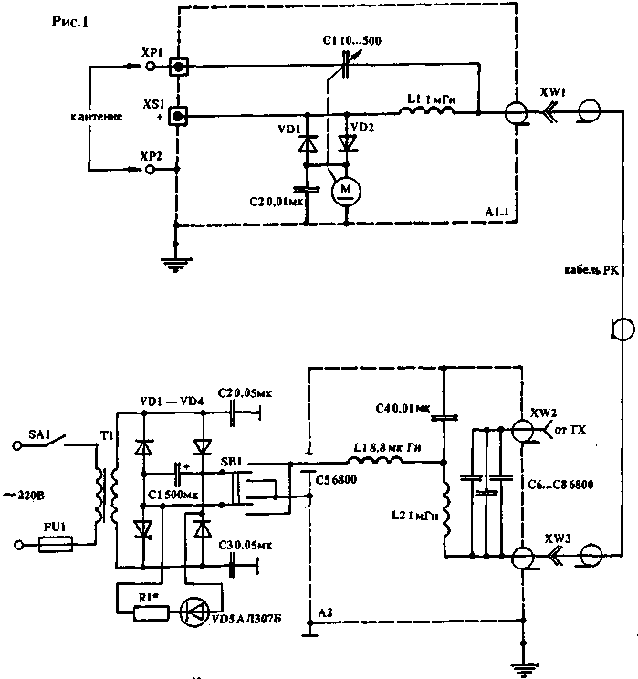
The device consists of two blocks. The antenna unit A1 is installed directly next to the vibrator. It is an essential part of the entire device. The main element here - KPE C1 air-dielectric, driven by a reversible DC motor with low speed. The entire device is in a metal case which must be sealed.
Version of the block A1.1, shown in the figure, entirely consistent SA2550 in which the rotor KPE C1 should rotate round without restrictions and to be well isolated from the axis of the engine or gearbox. The initial capacity C1 - 10…15pF maximum up to 500 pF at 28 MHz to 1700 pF 1.9 MHz. The gap between the plates KPE, as well as parameters of other parts of both units is chosen depending on the maximum power transmission device and the available engine.. it is only Necessary to note that all chokes installed in the device must be performed by a wire of appropriate diameter (depending on the current consumed by the engine) and not have the side resonances on the Amateur bands. This can be achieved by fulfilling their winding sections and progressive. The housing unit A1 must be grounded and to take measures to prevent the ingress of moisture, especially if it is installed outdoors. It is best to close another case made of a dielectric material.
The control unit A2 is installed in a room near the station. It serves as power supply and control a reversible motor in box A1. Electrical connection between the blocks is carried out by means of the coaxial cable of the required length and wave resistance. This cable carries both high-frequency voltage from the TX to the antenna in or out of RX and DC control voltage. The V1 switch three position control operation of the motor, i.e. the supply of the DC voltage of different polarity, which determines the direction of rotation of the engine. For decoupling the DC power source and the motor from the high-frequency voltage applied in blocks LC-filters and blocking capacitors, and to prevent the control voltage in the output stage of the PX transmitter and the antenna, capacitors C6, C7, C8, electric strength of which is also subject to a maximum transmitter power. To increase the reactive power of capacitors can be used a serial connection, unless the order will be of the capacitor to the desired power and voltage.
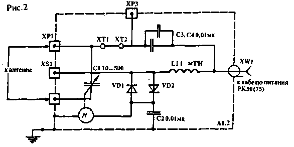
In Fig.2 shows a second variant of the circuit of block A1.2. It differs from the previous several great opportunities. Selection of the appropriate option block A1 depends on what type of antenna system and its coordination. In Fig.3 - 8 shows the different wiring diagrams KPE C1 to different types of asymmetrical vibrators.
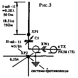
In Fig.3 shows how, by making unbalanced vibrator, 5% to 15% longer than a standard quarter-wave vibrator and using this device, you can get the opportunity to tune the antenna to resonance at any point in the operating range. In addition, an elongated vertical dipole agrees better with coaxial cable.
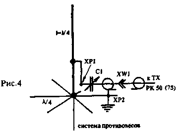
In Fig.4 shows an embodiment of the application device with a quarter-wave vertical dipole, fed by gamma-matching device. In this case, S1 performs the role of trimmer capacitor in the matching device and allows for improved matching of the vibrator with the power cable at various points of the range.
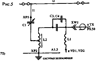
In Fig.5 shows the wiring of the block A1.2 to work with the G-shaped vibrator designed for one of the bands (160 or 80m). At these ranges at a short length of vertical part of the l-shaped vibrator has a low input impedance, and to align it requires the use of additional inductors or step-down transformer. They are connected to the terminals 2, HRS and the body of the block and jumper 1, HT removed.
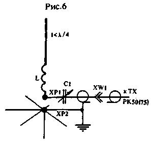
In Fig.6 shows the connection of C1 to the vibrator with a length less than a quarter wavelength, the extension having a coil mounted in the working part of the vibrator. The inductance of this coil is selected so that the resonance frequency of the vibrator when zamorochena KPE C1 was somewhat lower than necessary.
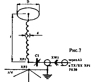
The same applies to the antenna shown in Fig.7 and described in [3]. Due to a significant shortening of such antennas have a very narrow bandwidth, and this device will allow it to be used effectively anywhere in the range.
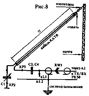
In Fig.8 shows the wiring of the block A1.2 to an inclined dipole, made of cut ribbon cable. The electrical length of the vibrator is selected depending on the used cable and close to a quarter wavelength. The range of 160 m permissible use ribbon cable for power and radioproval with two wires with a minimum diameter of 0.5 mm at a distance of several millimeters and having a good quality insulation. It is necessary to take into account the velocity factor.
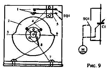
As already mentioned, the requirements for maximum capacity KPE C1 depend on the ranges on which an antenna. So how to choose KPE with a low initial and necessary for the LF bands maximum capacity of 1,000 pF and more than hard enough, you can apply additional switching contacts. They can also be useful in case you need to disable KPE C1. This version of the revision of the block A1.2 shown in Fig.9, where the numbers:
1 - a group of switch contacts;
2 - disc of insulating material;
3-axis KPE C1;
4 - 8-bolts MOH, M4;
5 - insulation fastening plate contacts;
6 - metal bushing for mounting the disk to the axis of the KPE;
7 - metal wall or shell of the KPE C1.
The device can be used for collaboration with the antenna described in "RL" N12/92, p. 38. OK3TDC [5] showed the possibility to use the antenna for 80-meter range, to work on 40 and 20 meters when connected in parallel to the supply line of capacitors of a certain capacity. The use of block A1.2 allows you to do this without a mechanical switch. Another possible option scheme include KPE C1 block A1.2 in full-length or shortened frame shown in "RL" N6/92, p. 45, Fig.2. In this case, it is included in the gap of the frame.
Literature
Author: V. Efremov; Publication: www.cxem.net