About the height of antenna installation
When choosing the design of transmit-receive antennas for Amateur radio stations in the shortwave has to take into account many factors, to find compromise solutions to many technical issues. One of them - installation height of the antenna. The ability of radio Amateurs in this area (regardless of where he lives - in the city or in the countryside) is very, very limited. Is there any optimal solution? To some extent the answer to this question is provided by experiments conducted DJ2NN[1].
It should be emphasized that to measure the dependence of the efficiency of the antenna height from its mounting on short waves is not easy. The greatest interest, of course, provide these data for large length of traces (i.e. for DX ties), and this means that the measurement results significantly affects the propagation of radio waves in the ionosphere (especially rapid fluctuations of the passage). Moreover, in the General case, these dependencies can have a different character for runs with different length and azimuthal orientation. To increase the reliability of the results can only repeated measurements, a set of statistical data.
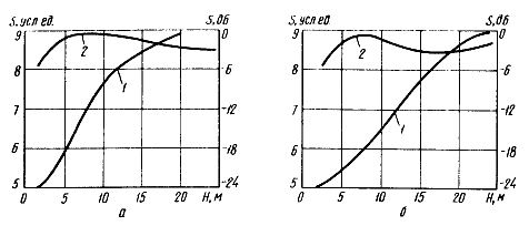
Fig. 1. The effectiveness of directed LW antenna height from its mounting (1 - DX, 2 - "near" area): a - 14 MHz band; b-28 MHz
DJ2NN conducted measurement of the dependence of the efficiency of the antenna height from its mounting on the Amateur bands 14. 21 and 28 MHz in receive mode signals DX stations (route length is not less than 5000 km). In addition, we measured and a similar dependence on the signals of stations in "near" zone, where the relationship is due to surface wave. In these experiments DJ2NN used antenna "wave channel", the height of the unit which could very quickly change within 2.5 ... 25 m. They were adopted special measures, which would rule out measurement errors caused by the detuning of the antenna at low altitudes installation (due to the influence "earth"). The results of these experiments for bands 14 and 28 MHz is shown in Fig. 1, a and 1, b. The General course similar dependences for the range 21 MHz is very close to the data shown in Fig. 1, and. The curves denoted by the numeral 1 refer to the measurements on signals DX stations, and number 2-input signals from stations located in the "near" zone Analysis of these curves allows one to draw several conclusions.
First, the measurement of short-wave antenna and development of its pattern on the field strength in "near" zone can not always provide objective information about its effectiveness in conducting DX ties. In other words, measurements in "near" zone is a necessary, but sometimes insufficient step in establishing a directed LW antenna. Secondly, in the altitudes of 2.5... 15 m the efficiency of this antenna on the bands 14 and 21 MHz varies greatly. You may experience a situation where more simple and easy two-element antenna raised to a height of 10 to 12-m, will be more effective than, say, a three-element antenna that radio Amateurs can't raise above 5...7 m (due to the higher mass, more bulky and heavy rotator etc).
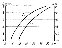
Fig. 2. The effectiveness of directed УSW antenna height from its installation: 1-band 432 MHz; 2' - 144 MHz band
And third, the increase in the height of the antenna above about 17 m not justified. The efficiency increases slightly, and the manufacturing costs and technical difficulties associated with the installation and operation of the antenna, increase many times.
Fig. 2 illustrates the effect of height УSW antenna on its effectiveness for bands 144 (curve 2) and 432 (curve 1) MHz. These measurements were carried out DJ2NN for the source remote is 20 km away and it is Interesting to note that in this case the dependencies have practically no tendency to saturation at high altitudes.
Non-directional antenna
Most of the Amateurs forced to be limited to installing only one antenna, which, of course, try to make multi-band and omnidirectional. There are many designs of such antennas in which these requirements are fulfilled to a greater or lesser extent. One of these antennas - "G5RV" (Callsign radio Amateur, who offered her [2] - is designed to work on the Amateur bands of 3.5-28 MHz.
The dimensions of the antenna and matching two-wire line is shown in Fig. 3.and, the antenna power is supplied coaxial cable with a characteristic impedance of 75 Ohms. Recommended installation height of the antenna above the ground or roof - about 10 m. If the span in which to install the antenna, less than 32 m, the end segments of the leaf antenna length up to 3 m can be left hanging down (i.e. to install the antenna in this case will fit the span of about 26 m). Antenna G5RV" in principle permits installation with only one mast in the form of "INVERTED V", but its performance is not noticeably deteriorated, the angle should not be less than 120°.
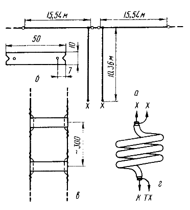
Fig. 3. Multi-band LW "G5RV": a simplified construction of the antenna. b - insulator; in - unit two-wire line: Mr. high frequency choke.
Homemade matching two-wire line is formed by two wires, the distance between them is kept constant insulators (Fig. 3,b) made of good proof, non-hygroscopic dielectric material (Plexiglas, the PCB, etc.) After appropriate impregnation can also use a wood or plywood. Wire line is placed in V-shaped cutouts at the ends of the insulators and fix small portions of the wires (Fig. 3. 0), passed through the holes in the insulators. Matching line should be going perpendicular to the blade antenna at least 6 m long.
For efficient operation of the antenna "G5RV on all bands the feeder must be connected to the transmitter via a matching device. Because of this antenna in the feeder are almost always there in varying degrees, standing wave, it is possible to apply the balun device (BALUN) for the transition from the matching line to the coaxial cable does not make sense. However, to reduce radiation from the outer braid of the cable (it. in particular, may cause interference to TV) it is advisable [3] from the top of the feeder to make a high frequency choke (Fig. 3. g). The number of turns 8 .. 10, the winding diameter of about 180 mm, coils fastened in three places with adhesive tape.
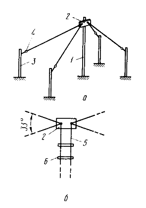
Fig. 4. Embodiment of a multiband antenna based on the "G5RW: a - antenna design: b - Central lock-up and connection of the feeder.
Another option mnogovershinnoe LW antenna, which is based on a "G5RV" [4], is shown in Fig. 4. and. On the main mast 1 height of about 12 m at an angle of approximately 30° to each other hung two paintings antenna "G5RV". The ends of these paintings through the insulators 4 are attached to the four auxiliary masts 3 height of about 6 m. In the center of the leaf antenna pairs are connected to a common two-wire line 5 (see Fig. 4.b), which is the same as in the usual "G5RV", overhead on insulators 6. For fastening the ends of the paintings on the mast 1 serves as the Central insulator 2. It should be noted that these dimensions are not critical. They can be varied within a wide range, focusing on the possibilities of radio and space available for the installation of the antenna.
In Amateur literature often describe multiband horizontal antennas constituting emitters connected in parallel (for example, half-wave dipoles) on a separate LW bands. This principle can be applied to create antennas with vertical polarization. The design of this tri-band LW antenna [5] is shown in Fig. 5. Metal mast 3, which forms the emitter on the 14 MHz band, mounted on a supporting insulator 2. In its upper part at a distance of about 350 cm from the reference insulator reinforced dielectric spacer 9. To the base of the mast are attached (and connected to it electrically) wire emitters 4 ranges on 21 and 28 MHz. The tension emitters provide nylon stretch marks 5 that are attached to them through insulators 6. It feeds the antenna coaxial cable 8 with a characteristic impedance of 50 Ohms, the Central conductor of which is connected to the mast 3, and the braid to the system of checks and balances 7. The lengths of all emitters differ from the values */4 for the appropriate range, due to the mutual influence of emitters. Is shown in Fig. 5 dimensions of radiators were chosen experimentally for minimum SWR on the working range.
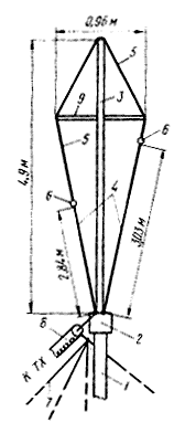
Fig. 5.
Variant wideband antennas [b], working at all LW bands, including 160 meters, shown in Fig. 6. The antenna is a wire emitter length of 22.6 m, at a distance of one third from the end of which is included LR-a chain that extends the frequency range.
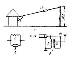
Fig. 6. LW antenna for bands 10..J60 m: a - General view, b-LR-circuit; in - matching transformer.
This circuit (Fig. 6, b) formed by a resistor of resistance R 370 Ohms (6 resistors 2.2 kω and a maximum power dissipation of 1 watt) and coil L (55 turns of wire with a diameter of 1 mm, the winding ordinary solid on the frame with a diameter of about 50 mm).
The antenna is connected to the feeder (impedance 50 Ohms) through a matching transformer (Fig. 6, in). It is formed on the annular magnetic core of ferrite with a diameter of about 50 mm with an initial magnetic permeability of about 20. Each of the windings has a 24 round wire with a diameter of 1 mm. connect the Antenna to the withdrawal from the 18th round of the secondary the winding. The connection point is selected empirically in establishing the antenna.
Adjust the antenna selection in the first turn of the coil inductance L and the connection point of the antenna to the matching transformer. The criterion is a minimum SWR within the Amateur bands. Although the article mentions the possibility of the antenna even in the range of 160 m, real, apparently, to obtain satisfactory characteristics can only at frequencies of 7 MHz and above.
The influence of "earth"
The above-described antenna, as well as many other "wire" and whip antenna, for its normal (effective) work requires good "electronic earth". In urban (and urban) conditions usually provide equivalent connection - balances. How many balances and how long can create a good "electronic earth"? Measurements show [7] that number is expected to exceed 20 ... 30. When multiple balances (case is very typical in Amateur practice) resistance losses is about 30 Ohms. It means that about 50% of the transmitter power is lost. In other words, it is worth considering that it is easier - conflict with the State inspection of telecommunications, raising in excess of permitted limits transmitter power, or add a few dozen balances to the antenna and to receive the same the effectiveness of radio in General.
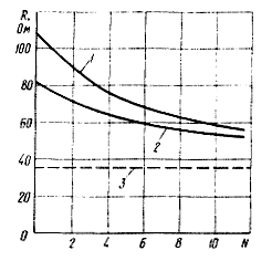
Fig. 7. The dependence of the input impedance of the pin from the number of counterweights
A typical dependence of the input impedance of a quarter-wave pin (theoretical value 37 Ohms) of the number of quarter-wave balances for various conditions (1 - dry soil, 2-wet 3 - theoretical value) is shown in Fig. 7. Not taking into account these dependencies, wondering what GP with three counterweights provides the CWS ~ 1 when powered coaxial cable 75 Ohm (theoretical SWR ~2). Becomes clear and effective operation of some vertical antennas in a wide band of frequencies - loss in the "earth" significantly expand the universe.
Notch contours for LW antennas
Antenna with notch contours ("Like w3dzz" and others like her) is widespread in Amateur practice. They are of appropriate characteristics, but from a constructive point of view is not very convenient. Particular difficulties (in the making or acquisition) causes the capacitor included in notch LC-circuit. He must have a definite value and a very high electrical parameters, working in conditions of exposure to atmosphere moisture.
Rejector circuit for the antenna type "Like w3dzz" can be made from a piece of coaxial cable braid which could create the necessary inductance, and "core- braid" will create the necessary capacity |8].
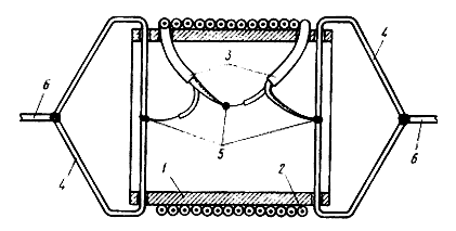
Fig. 8. The design of band-stop circuit on the basis of the coaxial cable
The design of the rejector circuit is shown in Fig. 8. On the dielectric frame 1 is wound coaxial cable 2. The ends of the cable 3 is passed into the holes of the frame and raspalaut (5) in accordance with Fig. Staples 4 are used to connect canvases antenna 6.
For a simple antenna with notch contours choice of parameters of the coil is quite arbitrary (we only need to provide the desired frequency of rejection). In the antenna "like w3dzz". in addition, you must have a definite relation to the inductance of the coil L and capacitance C - cannot be realized without this multi-band properties of the antenna.
Directional antennas
Rotating directional LW antenna - the dream of all the shortwave. However, to make a full-sized antenna ("wave channel", "double square", etc.) many hams not afford One reason for this - very limited on the roof of a residential house, which shortwave can be used to install the antenna (especially in houses-towers). That is why in Amateur radio magazines as often describe different variants of small single or multi-band LW antennas.
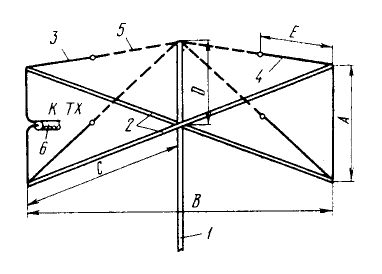
Fig. 9. Directional antenna "DOUBLE-D"
Antenna, a sketch of which is shown in Fig. 9, is called "DOUBLE-D" ("double Delta") [9]. Small in size, lightweight, it may well be the first design of shortwave wishing to enhance their Amateur radio station installing a rotating directional antenna.
On the mast at a distance of 1 D from its summit there are four struts 2 made of bamboo or wood, impregnated with a moisture-protective compounds. The ends of these struts and through stretching 5 fasten the fabric of the active element 3 and the reflector 4. Both paintings are made of copper wire or antenna cord and stretch - nylon cord. The configuration of the active element and reflector resembles the Latin letter D, hence the name of the antenna. Feed the antenna via a coaxial cable 6 with a characteristic impedance of 50 Ohms.
The length of the wire antenna elements in meters is calculated by the following formulas (f is the operating frequency in MHz):
A = b = 85,1/f
C = 60,2/f
D = 17,8/f
E = 34/f
The value of the frequency f are either in the middle of the corresponding Amateur band, or in the middle of his site, for the most of shortwave (for example, in the middle of the Telegraph station).
Based on data from [9], antenna "DOUBLE-D" almost as good as a two-element antenna "wave channel" according to the Directive gain and the ratio of the radiation back and forth. However, it has less bandwidth, as shown in Fig. 10, which shows the dependence of VSWR with frequency for (range 28 MHz) antenna "DOUBLE-D" (curve 1) and a full-sized "wave channel" (curve 2).
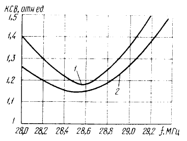
Fig. 10. Dependence of the coefficient of the standing wave with frequency in the range of 10 m for antennas "DOUBLE-D: two-element "wave channel"
Tune this antenna selection the length of the active element and reflector. At the resonant frequency of its input impedance is purely resistive in nature and is approximately 40 Ohms.
Using this principle of construction of the antenna, can be made multi-band design. In this case, each of the active elements, it is desirable to supply power to a separate coaxial cable. Experiments with dual-band antenna (14 and 21 MHz) showed that the installation on the same design elements in the second range does not change the directivity of the antennas. When washing both active elements even over one coaxial cable VSWR within both the Amateur bands does not exceed 2.
Compact trendease (14, 21 and 28 MHz) "double square" (Fig. 11) was proposed. 9Н1GL [10]. In size it does not exceed dvuhtsepochnyj "double square" on 21 and 28 MHz. This antenna essentially consists of two full-sized "double squares" on the bands 21 and 28 MHz, and the third band - 14 MHz is obtained by connection elements 21 MHz range load capacitance.
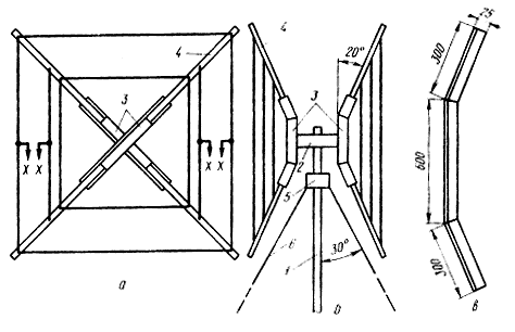
Fig. 11. Small triband dual square: a - front view; b - side view; b - configuration of the antenna elements
On the mast 1 is fixed a short traverse carrier 2, which in turn are mounted bracket 3 "hedgehog". The use of combinations "traverse carrier" - "hedgehogs" (each of them separately is widely used in "double squares") allows to obtain a very high point of attachment of stretch marks 6. The antenna rotates with the mast 1 (engine with gearbox installed at its base), so delays are attached to the intermediate bearing 5. Mast height of about 5.5 m, the bearing is set at 0.8... 1 m below the point of attachment of the carrier beam. In this case, when the maximum allowable angle between the mast and braces 30° point of attachment of the braces to the roof will be measured from the base of the mast is approximately 2.7 m.
The configuration of the elements of the "hedgehogs" 3 (they are made of a steel angle) is shown in figure 11. V. In bent parts of these elements are fixed U-bolts or clamps spacers 4 from bamboo. The length of the spacers is about 2.4 m. the Length of each side of the frame for the range 21 MHz is 3.6 m, and for the range of 28 MHz - 2,75 m.
Load capacitive elements for the antenna to work on the range 14 MHz, are located within the framework of the 21 MHz band (a little closer to the mast than the framework). They "disabled" four rejector circuits - two for each frame. The resonant frequency rejector circuits (up to connect to the antenna) -20,2 MHz. Structurally, they are made of coaxial cable as described in the previous section of the review. The circuits connected between the frame and capacitive loads at the points marked in Fig. 11.
The method of tuning the antenna elements on the bands 28 and 21 MHz no different from the standard. In the range of 14 MHz antenna set selection of the length of the elements - capacitive loads. If the change in the length of these elements significantly influence the parameters of the antenna on the range 21 MHz, then the ego suggests that notch contours configured inaccurate (i.e. not "disable" all capacitive load when working on the range 21 MHz).
When the antenna power of 50 Ohm coaxial cable VSWR do not exceed 2 on all three bands.
Literature
Hawker P. Technica I Topics. - Radio Communication, 1985, No. 4, p. 274-275.
Yarncy L. G5RV multiband antenna . . . up-to-date. - Radio Communication. 1984. No. 6, p. 572-575.
Hawker P. Technical Topics. - Radio Communication, 1982, No. 2, p. 142-143.
Dob'ns R. G. QRP. - Radio Communication, 1985, No. 3, p. 206.
Doncei D. Antena "sisargas" vertical para 10, 15, 20 m. - URE, 1984, No. 10, 572 n.
Johansson F. VK fi wireless antennas - en mliltihandantennen. - QIC, 1984, No. 12, s. 428.
Servik J. Short ground radial sistcms for short verticals. -QST, 1978, No. 4, p. 30-33.
Sommer R. Optimizing coaxial-cable traps.-QST, 1984, No. 12, p. 37-42.
Dodd P. Wire beam antennas and the evolution of the "Double-D". -QST, 1984, L 10, p. 21-23.
Hawkes J. M. A two clement quad 14, 21 and 28 MHZ antenna for restricted space. - Radio Communication. I984, No. 4, p. 300 - 103.
Author: B. Stepanov (RU3AX); Publication: www.cxem.net


