In the practice of the Amateur radio becoming more common antenna with vertical polarization. Specifically, you can highlight high-frequency SW-bands and УSW-bands 144 and 430 MHz, on which this antenna is now often used. This leads to a number of significant reasons, including, for example, the need to communicate with mobile and handheld radios, difficulties in finding places and the lack of required space to accommodate efficient antenna with horizontal polarization, the ability under certain conditions to reduce interference to TV reception, if it is applied symmetryone antenna with horizontal polarization. All this encourages us to look for different ways to improve the efficiency of such antennas.
In particular, all of the above applies to stationary antennas. For these cases are often used collinear antenna or multi-element directional antennas type "wave channel". Both, compared to the simple vertical antennas have a more significant size and weight [1,2]. In a recent compilation [3] describes the three-element antenna having a reduced size. In foreign literature such antennas are described in more detail [4...8] and has long been known as "HB9RU-Beam". Moreover, the sizes of these structures is minimal, i.e. the elements are made based quarter-wave antenna. These dimensions allow the use of directional antennas in mobile or portable, made for УSW bands 144 and 430 MHz. Moreover, in comparison with the variant described in the book [3], [4...8] there is no mention of the necessity to use additional balances.

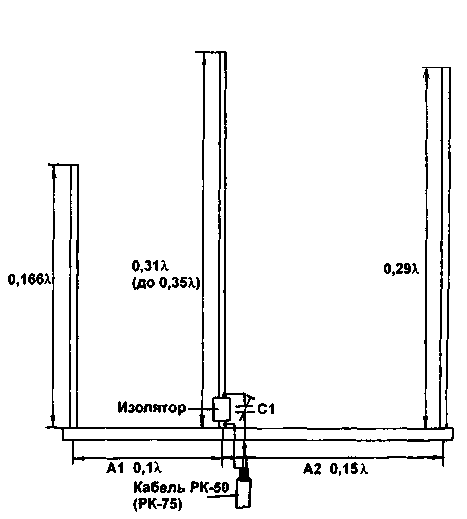
Fig.1
In Fig.1 shows the structure and given the size of the antenna, designed for operation on high frequency SW bands. Its main features - the lack of balances, which obviously performs metal cross member. Custom elongated vibrator allows to obtain optimal matched to 50-Ohm coaxial power cable. In the literature [4,5] provides the basic technical characteristics of the antenna:
- gain - dB;
- the attitude back and forth more than 15 dB;
- CWS - not more than 1.3 bandwidth of about 300 kHz.
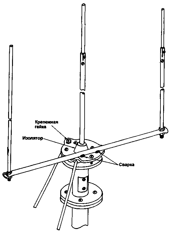
This design was repeated and tested by the author, but in the stationary system - if available under the base of the vibrator vertical load-bearing metal masts and two resonant balances. This technical the decision was due to specific existing conditions and concerns receive antenna system with low efficiency.
In Fig.2 shows the appearance of proven designs. Although confirm all the above characteristics in the process of testing the antenna failed, it was quite effective, and the selected design - sustainable enough to adverse environmental impacts.

Fig.2
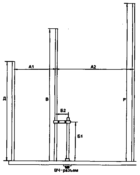
In Fig.3 shows a variant of the design of the antenna with gamma-alignment proposed in [8] for УSW bands 144 and 430 MHz.

Fig.3
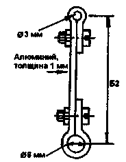
Individual elements of this design are shown in Fig.4 and 5. As the beam you can use an angle or U-shaped profile made of duralumin.

Fig.4

Fig.5
For the adjustment of elements at a certain resonance frequency in the upper ends of the tubes installed metal screws with nuts [4]. All main dimensions and data elements of both versions of the antenna shown in the table.
The dimensions of the antenna element data
Table 1
Range, MHz
Director D, mm
The vibrator In, mm
Reflector P, mm
The distance A1, mm
The distance A2, mm
The capacitance C1 (pF)
The distance B1, mm
Length B2, mm
Figure N
14
3560
6980
6120
2110
3170
90
-
-
1
18
2735
5440
4780
1650
2475
90
-
-
1
21
2350
4670
4100
1420
2120
80
-
-
1
24
1990
3960
3480
1200
1800
80
-
-
1
28
1745
3470
3020
1050
1580
70
-
-
1
50
990
1970
1730
595
895
50
-
-
1,2
144
380
520
610
170
287
-
135
45
3
432
126
170
203
56,6
95,6
-
45
15
3
The selection of the external diameter of the tubes and the thickness of their walls depends on the operating range, i.e. a specific length, and is largely determined by the need to provide structural strength. Most suitable for the manufacture of antenna elements are tubes made from duralumin. The elements, especially the vibrator, it is better to perform the type telescopic - tube of different diameter. After the final adjustment of the antenna position of the tubes is fixed by means of bolts, as shown in Fig.2.
Literature
1. Radio, 1980, N3.C.58.
2. LW, 1996, N2, 38 C.
3. Antenna satellite, LW, УSW, CB, TV, BT. -M.:
Symbol-P, 1998., c.238.
4. Amaterske radio, 1976, N8, c.313.
5. CQ DL, 1975, N 4.
6. Schlatter E. Three-element vertical Beam. OLD MAN 44,1976, N5.P.22-24
7. OLD MAN 46,1978, N1.
8. Rohlander W. HB9RU-Beam for 144 and 430 MHz. - Funkamateur, 1982, N10, c.509.
Author: V. Efremov (UA6HGW); Publication: N. Bolshakov, rf.atnn.ru


