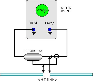
When establishing a shortwave antennas you can use the meter response (X1-19B, X1-7B). Its output is connected to the input via the RF head (Fig. 1), and the connection points connecting the antenna.

Fig.1
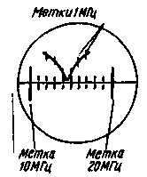
The setting starts with the determination of the resonant frequency of the antenna. Depending on the type of antenna on the screen will be observed or the "hump" (wave vibrator and other antennas with high input impedance at the resonant frequency), or "failure" (half-wave vibrator. derivatives of the antenna). Adjusting the antenna, ensure that the maximum (minimum) of the curve on the screen of the meter response coincided with the middle of the operating range. Frequency control on labels on the screen. The approximate form of the frequency response of the antenna "Ground PIane" (without feeder) on the 14 MHz band shown in Fig.2.

Fig.2
Under the supervision of the characteristics of multi-element antennas visible "feedback" from each element, which greatly simplifies the configuration process.
In this way it is possible to measure not only directly at the input of the antenna, and is connected through a feeder, for example, coaxial cable. It is observed the total response of the feeder and the antenna that gives the possibility in the case of resonant feeder to pick up its electrical length.

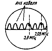
Fig.3
In Fig. 3 shows an exemplary view of AFC "Inverted Vee" on the ranges of 3.5 and 7 MHz is connected with a coaxial cable with a characteristic impedance of 50 Ohms.
Authors: I. Kawecki (UQ2G1G), S. Hochberg (UQ2MU); Publication: www.cxem.net


