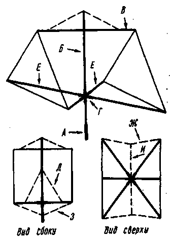
The proposed construction of "DELTA LOOP" is simple. For its production requires a bit of material. It has a low windage. The antenna can be mounted in sections on the working height. The advantages and relates her negotiationsthe (you can use any combination of ranges from 7 to 28 MHz). Moreover, there is a possibility to place the frame on each range for optimal a distance from each other and 0.2 lambda.
The antenna design is schematically shown. For simplification it shows a frame of the low frequency range. Framework for the remaining ranges are inside. Both elements - the active element and the reflector have the same dimensions. To configure the reflector used in resonance of the extension cables. All dimensions of the antenna required for its repetition in the table.
Table 1
Range, MHz
Side frame, cm
Loop length, cm
The distance between frames, cm
The frame height, cm
The length of the strut from the mast, cm
7
1450
100
869
1240
844
10
1011
70
607
864
589
14
724
60
434
619
422
18
564
50
338
482
329
21
483
45
289
412
282
24
410
40
246
350
239
28
359
40
215
308
210
The antenna is assembled in the following sequence
Previously on the traverse In must be secured (through insulators) framework for the low-frequency range as well as post insulators for active elements and reflectors for remaining anticipated ranges and to pass them in nylon cords. On the mast (the gear) And set the rack B with traverse and a crosspiece In G If necessary, to the rack B cable stretch marks D, the ends of which hang freely.
On the struts E in the pre-marked locations alternately through insulators attached to the corners of the other ranges. At the ends of the struts E tie streamers W floating insulator and I. Length stretch W must be greater than the distance between the framework (see table) the very low frequency range. To the ends of the struts E tie streamers 3. Choose strut E in turn is inserted into the yoke G and record. The cross-piece G in position fixed with locking screws.

Using stretching and 3 and, pull extreme frame and fix struts E. Nylon cord threaded into the insulators traverses In, pull the rest of the frame. If there is stretch marks D them tied to the struts E as far as possible from the mast.
For struts E, you can use bamboo, wooden slats, dural tube, divided into two or three sections insulators. Stretch marks W and 3 are made of steel, galvanized lengths of 50...80 cm wire with a diameter of 1.5..,2 mm interconnected insulators. The latter can be made of fiberglass thickness of 4...8 mm as stretch marks And use a steel wire having a diameter of not less than 2.5 mm, as they account for the bulk load when the wind is strong.
Active vibrator feed from the corner and the Central conductor 75 Ohm coaxial cable is connected to the vertical frame part and the screen to horizontal. This ensures the efficiency of the antenna at low altitude its suspension. Reflector tuned to the working height, using the simple indicator of field strength. It is necessary to achieve maximum radiation "forward".
In conclusion, it should be noted that the gain of the described antenna is comparable with the strengthening of the "double square" - 6...8 dB, but the total efficiency is higher. This was, incidentally, mentions I in many Amateur radio handbooks, such as the "ARRL Handbook".
Author: Nicholas Lawrece (UX0FF), Izmail; Publication: N. Bolshakov, rf.atnn.ru


