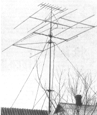
The antenna, which will be discussed (pictured in the Intro it lower), built on the base of the antenna proposed hb9cv please back in the sixties. Here's what it says in [1].
"Antenna consists of two vibrator unequal length, in parallel in the same horizontal plane at a distance l/8. Both active vibrator.
When a selected distance l/8 between the best vibrators unilateral directivity of the antenna is obtained then, when the current in the back of the vibrator (the reflector) lags the current in front the vibrator (the Director) at 225°"
In another publication ([2]) shows the results of comparison of this antenna with other already known.
"The gain of a two-element antenna with both active elements - referred to there, is equivalent to the amplification of the full-size three-element antenna with passive Director and reflector. If values are equal the gain of the two-part system is lighter and easier to constructive respect and has a smaller moment of inertia and windage with active Antenna food allows you to get more radiation suppression Coefficient ago... the gain of such antennas 3.4 dB higher than that of the antenna with a passive reflector, and the maximum suppression of the radiation back is 40 to 50 dB, while in passive systems, it does not exceed 25 dB"
Both authors provide mainly information about the electrical parameters of the antenna, which, of course, important, but saying little about its design, reliability.
According to the data given in [2], for example, it turns out that one of the elements in the range of 20 m, is attached to the traverse should have an overhang of about 5.5 m, freely positioned in space But in adverse weather conditions existing strength may be insufficient.
The author of this article applied strap connecting elements and which provide structural rigidity in the horizontal plane. Suspension supporting elements converge on the mast above the plane of the antenna. This is achieved stiffness in the vertical direction. The design turned out pretty solid. The antenna is in the range of 20 m is operated for more than four years without repair and is in good condition. She is survived dust storms, ice, winds.
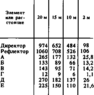
Schematically part of the antenna shown in Fig. 1. The sizes of its elements in a variety of ranges at tube diameter 30 mm are given in the table. For the initial size of the active vibrator taken 0,46 l, reflector - 0,5 l. Note that the length of the elements depends on the diameter of the pipe.
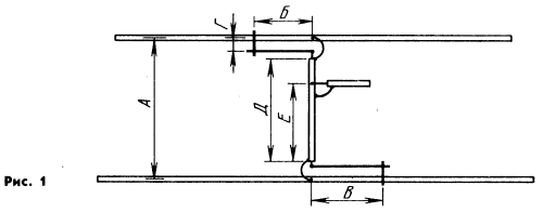
It should be said about the power to the antenna via a coaxial cable RK-75. The necessary phase shift of 225° is obtained. The shift of 180° is due to the fact that matching device connected to different shoulders of elements (one to the right, second to the left).
Another 45° provides a phase-shifting the line joining the elements.
To calculate the phase-shifting line is easy. Coaxial cable electrical length 0.5 l changes the phase by 180°. Therefore, to obtain a shift of 45°, the desired cable length of 0.125 l. Its the same geometric length will be less and many times - depends on the velocity factor. If you use coaxial cable with polyethylene insulation between the center conductor and braid having a velocity factor of 0.67, while the wavelength of 21.2 m, 'll need to cut
Lгeoм=Lэлeктp x Cukor=0,125 lKyкop=0,125x21,2x0,67=1.78 m.
But the phase-shifting line of such length to connect the antenna elements is impossible - the distance between them 2,65 m. Therefore it is necessary within reason to lengthen the cable. So, in this case the minimum length of an additional piece of cable equal to 2.65-1,78=0,87 m added To a segment in 0,87 m did not modify the phase shift (45°), the feeder needs to be attached to the middle of the extra piece. In practice, in the manufacture of phase-shifting lines it should not be set pieces (1.78 m + 0,435 m + 0,435 m). The cable length of 2.65 m is connected with a feed line at a distance 2,215 m from the end to be connected to the reflector.
It is more convenient to use extra piece of cable slightly longer than the minimum required, for example 1 m. Then the total length of the phase-shifting line will be equal 1,78+1=2,78 m. the same Feeder is attached at a distance 1,78+0,5=2,28 m from the reflector.
The Central conductors of the cable phase-shifting lines connect to the matching devices, braid by the middle of the elements of the feeder to the Central wire of the phase-shifting lines, and braid - to the braid. The author used a cable RK-75-9-13. Experiments with cable RK-150-4-11, recommended in the literature, some benefits not revealed.
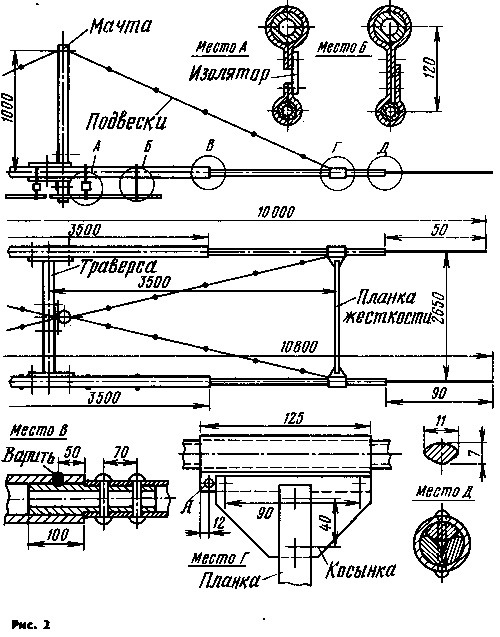
During the construction of the antenna (Fig. 2) we used the available materials. Cross member is made of one-inch steel water pipe (external diameter of approximately 33 mm). To the ends of the pipe are welded strap dimensions HH mm four holes with a diameter of 6.5 mm for the two clamps of fastening elements. The total length of the yoke with straps 2,63 m cross member attached to the mast via a square plate of size 150X150 mm of steel with a thickness of 4 mm clamps with M10 threaded hole.
Elements - teams. The middle part is made of half-inch steel water pipe (outer diameter of about 21 mm) with a length of 3.5 m.
Two sides added segments of the dural tube of 16 mm diameter with a wall thickness of 1 mm.
The pipe is obtained from the rings for gymnastics. It was cut at the junction of the tightly filled with dry sand, and then slowly (over 3...4 h) rectified.
In steel pipe (see Fig. 2) insert the machined internal size of the spacer (In) and is welded at three points through pre-drilled through 120 ° hole diameter of 6 mm On the exposed end of the spacer is wearing tight warmed dural tube. Additionally it is fixed with two aluminum rivets with a diameter of 5 mm.
In the free end of the dural tube insert molded tire from three-wire electrical cable and stuck it in two short segments of the same tire (choice E). Additionally, the joint is fixed with two aluminum rivets with a diameter of 3 mm.
The departure of the tire on the active element is 0.5 m, the reflector - 0.9 m.
At points spaced from the yoke of about 0.7 length of polyvibrating, the antenna elements are interconnected wooden slats rigidity section 20X30 mm (the G spot). The pipe element set dural clamp and fix the two M6 bolts. On top of the nuts on the bolts wear holes headscarf from fiberglass (PCB, Micarta) with a thickness of 4 mm and fix it with nuts and washers.
Scarves with pre-inserted into force cuts strap stiffness and record (through the washers) two steel rivets with a diameter of 4 mm On the clamps from the traverses made an extra hole And a diameter of 6 mm for mounting brackets.
For the manufacture of suspensions use a tourniquet made of three enameled copper conductors with a diameter of 1 mm.
The suspension is assembled from lengths of 1 m, connected through porcelain insulators - Marinova or rollers, and is attached to the mast at a single point, located at 1 m above the plane of the antenna.
The matching element is made of steel pipe with a diameter of 12 mm. It is attached to the item through the glass fibre laminate insulator (location A) and the movable clamp of sheet steel with a thickness of 1 mm (place B).
It should be borne in mind that when you use parts made of dissimilar metals at the point of contact there galvanic couple that Deplete over time the contact surfaces, especially when wet. Is affected by the contact between the parts, copper and aluminum alloy.
The mast is rotating, telescopic, consists of two parts. Lower (outer) pipe - steel 2.25 inch length of 6 m. it within 0.5-1 m of drilled through holes with a diameter of 6.5...8.5 mm in order to be able to fix it by pin inner tube when lifting it. The inner tube - polutoradyuymovy, a length of 7 m. the lower tube top wearing (with a gap of 0.2...0.5 mm) steel flange for attachment of the three strains (Fig.3).
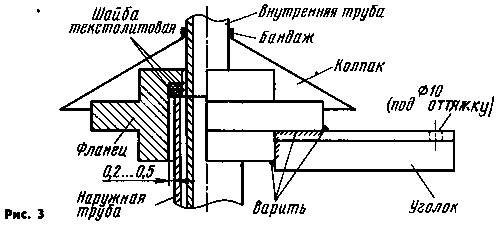
The depth of the grooves 30 mm, welded To the flange evenly around the circumference of three steel angle size HH mm length 300 mm with holes for attaching braces. The use of protruding corners reduces the extra tension of the guy wires during rotation of the mast. The flange rests on two textolite (glass fibre laminate is not suitable!) rings that retain well filled with grease ciatim-201, grease). The use of ball thrust, roller bearings is not justified.
The design of the flange for attachment of the braces of the second tier is similar. This flange rests on the steel ring, rigidly fixed on the inner tube of the mast. Before raising the antenna above the flanges install protective caps from roofing felts, roofing material or galvanized iron. All the connection details in the design is painted twice automotive enamel or red lead.
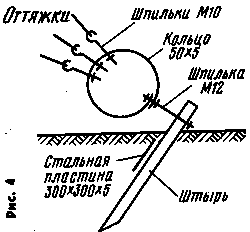
Delays need to produce from two to three twisted wires (galvanized steel, copper; steel wire rope should not be used). Single guy very unreliable. The lower ends of the braces is attached to the pin embedded in the ground, through a steel ring with a diameter of 150...200, a width of 50 and a thickness of 4...5 mm (Fig. 4). The ring may be made from a strip of connected overlapping.
Too pull the backstay should not - it will only hinder the rotation of the antenna, and in winter can lead to their breakage.
In the upper part of the outer pipe, stepping back 50 mm from the edge, drill three holes spaced evenly around the circumference, and cut the thread M6.
Stepping back 0,5...1 m, drill three similar holes. After lifting the inner tube M6 bolts with sharpened to taper the ends of her centered and securely.
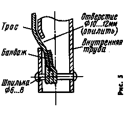
The cable for lifting the inner tube attached to its lower end. The design of this unit is shown in Fig. 5.
Before lifting the rope is passed through a roller mounted on the flange of the first tier of stretch marks and is fixed on the simplest collar attached to the lower part of the mast. As extensions of the inner pipe moves the pin on which it rests.
The antenna mast rests on a steel ball with a diameter of 15 mm from the bearing. On the outer tube at the bottom of fortified gear with a diameter of 600 mm (its core is machined on the machine tool, and the crown used by the flywheel automotive or tractor engine). Using simple gear-worm reducer it is connected with a 50-watt brushed motor.
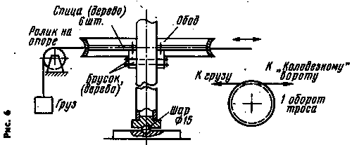
Driving device can be made more simple - at the base of the rim of a Bicycle wheel (Fig. 6).
When configuring the antenna may it is set on a higher elevation, in the open, but so that it was the access to the elements it was about three meters above the ground).
First of all, Gere determine the resonant frequency of elements (no matching devices and phase-shifting lines). The coil of the device when it is brought to the middle element. The resonant frequency of the active vibrator should be 14,15 MHz, reflector - 14,05 MHz.
If the resonant frequency was higher than desired, it is necessary to check whether the short vibrators - and, if necessary, to lengthen them. If the resonant frequency is less, set the matching device and the phase-shifting line. The feeder is connected via a rigid coil (4-6 turns with a diameter of 15 mm; the rest of its features are not critical).
Putting her GEAR, determine the resonant frequency of the whole system - it should not exceed 14,15 MHz.
After that achieve minimum SWR and optimal values of the radiation back and forth. This can be done using only the transceiver and the indicator field.
The antenna connected to the transceiver, and an indicator field to find the maximum of radiation in range and direction. If it is in the beginning of the range, the elements longer required, if at the end - shorter.
By setting the resonance frequency, the displacement of the clamps on the coordinator devices achieve low VSWR.
The last configuration step is the removal of the directivity diagram of the radiation at the operating altitude. Optimal height of - 0,5 l (10.5 m) and l (21 m); intermediate the radiation pattern may be distorted. So, at a height of 6 m chart is close to circular.
The field indicator feature at a distance of 20...50 m from the antenna, preferably at the same height as her. Include the transceiver in CW mode and by turning the antenna, every 15...20° record the meter reading.
According to the obtained points chart (Fig. 7).
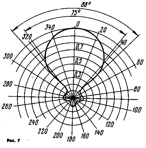
In the author's copy of the antenna SWR at the frequency 14,18 kHz was less than 1.1, the edges of the range did not exceed 1.6, which is due to some escapologist because of the small diameter ends of the elements. The beam width at the level of 0.7 in the horizontal plane - about 75°. Posterior lobe is weak.
Literature
Author: G. Butorin (U5MH), Anthracite; Publication: www.cxem.net


