Among the problems faced Amateurs-Amateurs, basic, perhaps, is the problem of making effective enough and at the same time is not very complicated in construction of the antenna. There is no doubt that the best results can provide a rotating directional antenna. However, almost all of the total antenna types are bulky and structurally complex, which complicates the use of their many fans.
In the article published below proposed method significantly reduce the geometric dimensions while maintaining a sufficiently high efficiency antennas, which undoubtedly will be of interest to Amateurs.
The author deliberately did not give specific antenna design, as it hopes that a wide range of Amateurs will experience the described method on the antennas with different degree of reduction for different ranges with different design.
In recent years, in the pages of the Amateur radio press published a lot of variety descriptions high small-sized antennas in which electrical lengthening the resonant length is achieved by using reactive elements (inductances, capacitances, line segments). By reducing the geometric dimensions is facilitated antenna installation and simplifies the design of the supporting devices.
Some hams refers to such antennas with a certain skepticism, explaining that any geometrically reduced antenna works full-sized worse. It is impossible not to agree. Really, any kind of shortening of the vibrator decreases the area enclosed by the plot of the distribution flowing through it current (hereinafter called the "current size") and, therefore, the efficiency of the antenna. However, the degree of reduction efficiency depends not only on the degree of geometric reduction, but also by the way the electric antenna system. In addition, sometimes it turns out that a smaller antenna in actual conditions works even better full-sized due to the redistribution of energy loss and radiation, such as installing a reduced antenna at a much higher altitude above the surrounding terrain. Small-sized antenna, obviously, can also attract the attention of hams that do not have in effect any reason possible to install a full-sized antenna.
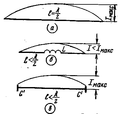
In Fig.1 and shows a full-sized half-wave vibrator in Fig.1,b - vibrator electrically lengthened by the inclusion in the antinode of the current of the coil L, in Fig. 1,a vibrator, electric elongation which is achieved due to the capacitive load at the ends. For each vibrator shows the current distribution along it. As can be seen from the drawings, the maximum area of the current is observed in the full-sized vibrator.

Fig.1
For the other two vibrators can see that with a substantial degree of electrical lengthening the size of the current in case of inclusion of capacity committed to the rectangle with height Imax, and in the second case - to the triangle with height I<Imax. The square of the current in Fig.1,in approximately equal lIмакс, as in Fig.1,b - 1/2lI. Thus electrical extending with capacity more profitable than using the inductance. It should be noted that the greatest effect is obtained only when you turn inductors in point loops of current, and capacitors - point loops voltages. While the items to other points of their reactance needs to be more. Line segments are used as elements of the electrical lengthening equivalent capacitance or inductance and depending on this are included in certain points of vibrators.
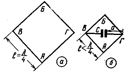
In Fig.2,and shows a square vibrator, turned one of the corners down. For a symmetrical antenna power at point a or B the antinode of the voltage will be at points b and G, and the antinode of the current at points a and B. the Vibrator can be electrically lengthen, including the inductance to break the wire at point a or B, or the capacitance between points C and D. the Latter method in this case is more favorable. As a result, we get a vibrator in the form shown in Fig.2,b geometric dimensions less than those of the square in Fig.2,but with the same resonant frequency.

Fig.2
The purpose of the practical test feasibility of electric lengthening square antenna with capacitance experiment was conducted on the reduced model at a frequency of about 100 MHz. The square is made of a wire diameter of 1.2 mm, the size of the side of a square equal to 76 see the Results of the experiment are shown in table 1.
Table 1
but, cm
C, PF
fрез, MHz
0
0
102
10
0
101
20
0
98
30
0
97
40
0
96
50
0
94
50
8
65
50
15
54
50
20
50
As the table shows, with the increase of the wire length a (Fig.2,b) resonance frequency of the square is reduced, although the capacity is not yet connected With. This is due to the fact that the horizontal wires electrically lengthen the antenna educated at the expense of the additional capacity. When connecting capacity equal to 20 pF, the resonance frequency of the vibrator was reduced by half compared to the original.
Estimated values of efficiency depending on the relationship of the sizes of the small-sized antenna to normal size without losses in the insulators shown in table 2.
Table 2
The ratio of the sizes
efficiency compact antenna relative to the full-size, %
Electrical extending with capacity
Electrical extending with inductance
0,9
~99
85
0.8
95
70
0.7
90
55
0,65
85
50
0,6
80
40
0 55
75
35
0,5
70
30
Electrically elongated vibrators are the elements that can be assembled multi-element antenna. Below we consider the design of the "double square" made from the elements, elongated electrically through the vessel.
If the feed point of the antenna to select in the top And, in the case of electrical symmetry of the antenna, the voltage at point B will be 0. The voltage at point a will depend on the power supply circuit of the antenna. So. when applying widespread among radio Amateurs scheme g-matching the voltage at point a will also be close to zero. Generally speaking, it can be used as a vertical rod metal pipe, not insulated from the wires of the vibrator. However, with a slight violation of symmetry in a vertical bar will appear current, which will disrupt the normal operation of the antenna.
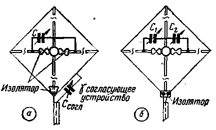
The role of the horizontal part of the vibrator can perform supporting metal rod, but it needs to be broken in the middle and isolated from the vertical rod. To the same point on the horizontal rod connects trimmer variable capacitor. A sketch of this design is shown in Fig.3,and.

Fig.3
In Fig.3 b shows a design in which we use two capacitors (C1 and C2) Power frame is a cable without a matching device. The rotors of the condensers are at a low potential, approaching zero when the symmetry of the antenna. Changing the ratio between the capacitances C1 and C2, can be symmetrical antenna. If your pet, then as capacitors, you can use a double block.
The value of the capacitors depends on the range to which the antenna and the degree of its electric lengthening. For all practical cases it is sufficient maximum capacitance of 50 PF.
Special attention should be paid to the insulators, since they are included in the voltage antinodes and largely determine the magnitude of the losses of high-frequency energy, you Should use the insulators made from materials with low losses (porcelain, polystyrene, polytetrafluoroethylene, etc.).
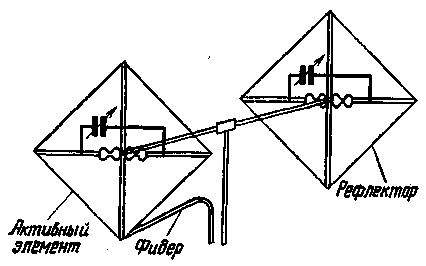
The passive antenna element is the same. The distance between the vibrator remains the same as for full-sized antennas. General view of the two-element antenna shown in Fig.4.

Fig.4
Specific dimensions of the antenna for an Amateur band are not shown, since they depend on the desired degree of reduction of the geometric dimensions and the dimensions of the supporting structure components.
Possible bug when marking the length of the wire is easily offset with the antenna tuning capacitor C.
Author: Ing.With. Bunimovich (UB5UN); Publication: N. Bolshakov, rf.atnn.ru


