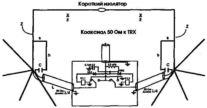
Physical realization of switching is very simple (Fig.1). Must be switched using relays feeder, releasing it from the active element (and turning it into a reflector) and connecting it through another gamma-Aligner to the reflector (and turning it into an active element).

Fig.1
If you want the amplification was directed to the left - capitivate left element; if the right - capitivate right. Nespecially element remains broken at the point of feeding. This is important because it is necessary that between the coaxial cable and point-feeding the reflector was electric gap. The analysis shows that shorting of the feeding point of the gamma-ray Aligner passive element requires additional wires gamma coordinator to obtain the necessary detuning of the reflector. Of course, in reality it is not very practical to change the point of feeding coaxial feeder if you want to switch directions. However, the requirement to leave open unused feeding point narrows the range of possible devices to switch. Recall that the short-circuited segment of the transmission line is a quarter wavelength looks from the second end as an open circuit and serves as a key during the development of the switching device.
Midway between the two vertical drops antenna "Box" is a shielded box containing two switches and extending from each of the gamma-ray Aligner to the box 50 Ohm cables with a length of l/4. One of the switches or connect this cable with the cable going to the transceiver, or, in the second position, it short-circuits to the ground. The second switch does the same thing, but in reverse order. If these conditions are met, one gamma ray Aligner will be energized, while the other will be broken at the point of feeding. When you switch they switch places, as well as the radiation pattern.
Control signals are fed via a coaxial cable to power the antenna. Therefore, the necessary special isolation for signal separation.
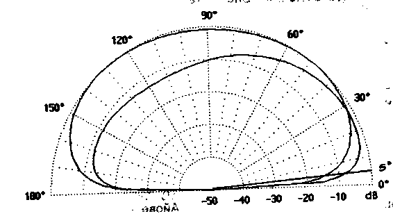
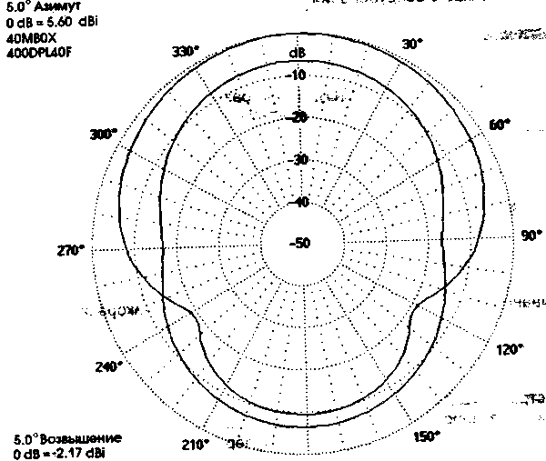
Vertical radiation pattern for the range 40 m shown in Fig.2, and azimuthally in Fig.3. Both graphs superimposed on the plot of a typical half-wave dipole.


In table.1 shows the geometrical dimensions of the antenna for LF, and tab.2 - dependence of its parameters on the frequency in the range of 40 m.
Center frequency,kHz
X
Z
s
h
c 1810
128,0
70,0
2,0
14,0
470
3525
67,4
35,0
2,0
6,5
390
3600
64,8
35,0
2,0
6,5
390
3795
58,0
35,0
2.0
6,5
330
7200
32,4
17,2
0,7
4,0
200
Antenna "Box" has a relatively good performance on 40 meters, but in this range dipole at a height of 40 feet above the ground, becomes a worthy opponent.
Frequency, kHz CWS Gain, dBd F/BdB 7200 1,96 5.95 5,02 7025 1,83 6,07 5,47 7050 1,70 6,20 5,96 7075 1,57 6,31 6,49 7100 1,46 6,41 7,07 7125 1,35 6,49 7,7, 7150 1,25 6,56 8,43 7175 1,16 6,60 9,21 7200 1,08 6,62 10,10 7225 1,02 6,62 11,47 7250 1,05 6,61 12,19 7275 1,11 6,56 be 13.42 7300 1,17 is 6.51 14,89
At this range it has less gain than 80 m Antenna requires high-quality land. A simple pair of opposite radial wires may not be enough.
As mentioned in the beginning of the article, the antenna is inefficient in the range of 20 m or more high. On 20 meters it loses a typical 3-element Yagi at a height of 50 feet to about 10 dB. Designing it for two meters is a waste of time. However, for bands 160, 80 and 40 m its alternatives significantly worse. Build it for one of LF and you - "giant" DX!
Author: T. HULICK (W9QQ); Publication: N. Bolshakov, rf.atnn.ru


