Description shortwave antenna "IIIDX antenna operating in the bands 80, 40, 20 and 15 m published by the American shortwave W3JHR. The antenna is a vertical pin height of about 15 meters without the braces, the base of the mast is grounded.
In Fig. 1, shows the directivity in the vertical plane curves and current distribution in the antenna on 40 (Fig. 1,a), 80 m (Fig. 1,b) and 20 m (Fig. 1,in).
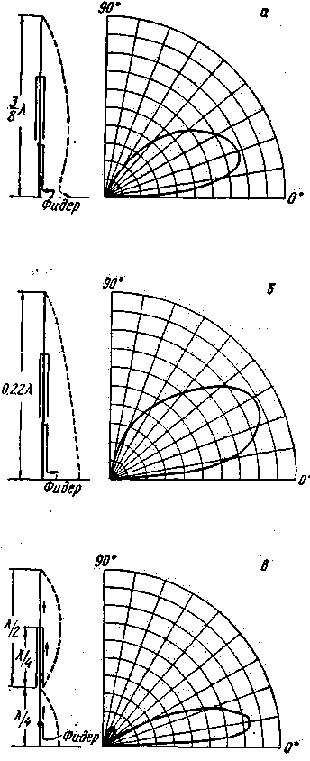
Fig.1
The values of the standing wave ratio (SWR) on 40 m and 20 m close to unity, in the range of 80 meters the SWR varies from 1 to 3.9 MHz to 1.7-3.8 and 4 MHz.
Structurally, the antenna is made of four aluminum tubes of different diameters, Inserted one into the other and fastened by four bolts at junctions (see Fig. 2).
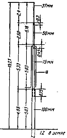
Fig.2
The dimensions of the antenna in Fig. 2 are given in meters and millimeters. The point of attachment of the gamma-matching device to the mast for each range is shown in Fig.3.
The coaxial design of the glass and (Fig.2 and Fig.3) consists of six aluminum wires tightly stretched on four aluminum rings. The upper and lower rings are made from strips of aluminum with a thickness of 6 mm and a width of 25 mm. Two middle rings are sized h mm Inner diameter rings 230 mm Top ring Cup is electrically connected to the mast, the rest of the ring is isolated. To the bottom ring two cords are attached, holding the glass in the tense condition.
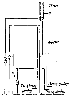
Fig.3
Antenna power is 50-Ohm feeder. The agreement made in the form of "gamma". Tube "gamma" aluminum with a diameter of 25mm. The lower ends of the tubes are secured to the insulators at a distance of 500 mm from the ground (Fig.4,b). The upper ends are attached to the mast aluminum brackets (Fig.4,a).
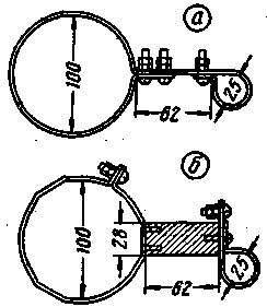
Fig.4
Setting "gamma" is the capacitors on each band separately. The block diagram of the configuration shown in Fig.5.
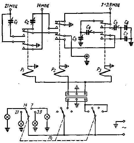
Fig.5
Capacitors C1, C2, C4 110 PF; C3-750 PF, C5 150 PF, C6 and C7 1000 PF operating voltage 5 kV Power relay is powered from the AC mains. To improve the antenna ground buried in the ground 4 wires, two of them with a length of 1800 cm and the other two from 1050 to 1500 see These four wires are attached to an aluminum bracket, attached at the base of the antenna mast.
Literature
Publication: N. Bolshakov, rf.atnn.ru


