


")

This antenna (Fig. 1) not original radio solution, but the design is interesting because it can be installed in the edge of the roof of a house. It consists of two electrically independent antennas: frames (DELTA LOOP) in the range of 20 meters and shorter pins (GP) in the range 80 meters.
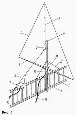
The mast 1 with a length of about 3 m, which supports DELTA LOOP and part of the GP, reliable is fixed to the fence 2 on the edge of the roof. In the upper part to the mast via insulating plate 4 is attached to the radiator the range of 80 meters with a length of 5.3 m, made of three lengths of thin-walled duralumin tubes are inserted one to another. To the lower part of the radiator 3 is connected to the conductor 5 by a length of 4.3 meters, supported by a dielectric stretching 6. He goes to the matching unit 7. In the lower part of the mast 1, just above the fence 2. attached dielectric pipe 8. It consists of two rods with a length of 3.5 m. the pipe supports the lower part frame 9. In the upper part of the frame is attached to the radiator 80 meters band through a dielectric insert (Fig. 1, not shown).
On the dielectric plate 11, the retaining rod, and matching is the transformer 13. Two banners 12 further fixed mast. Antenna feed via a separate coaxial cables 10 and 14.
A schematic of the antenna depicted in Fig. 2.
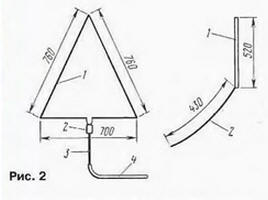
Frame 1, which has an input impedance of about 120 Ohms, zapityvat through balun transformer 2 and transforming a quarter-wave line 3 with a characteristic impedance of 75 Ohms. Power cable 4 is used with a characteristic impedance of 50 Ohms.
The construction of the upper insulator frame shown in Fig. 3.
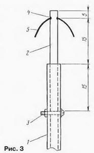
In the upper segment the pipes of the radiator 1 to the range of 80 meters insert a core 2 of a dielectric material. Screw with nut 3 does not allow the rod to fall into the pipe. In the upper part rod has a through hole 4. through which passes the wire loop 5.
Matching device range of 80 meters (Fig. 4) consists of the extension coil 8 and the inductor 5. The coil is wound on a frame with a diameter of 6 cm and a length of 25 see It has 50 turns of bare copper wires with a diameter of 1.6 mm, the winding Step - 1.6 mm. Sheath of the supply cable 4 is connected to the end of the coil, and point them the connection conductor 6 to ground metal fencing. Central cable conduit connected to the outlet 1 of the coil (about 1.5 turns, starting from the cold end of the coil).
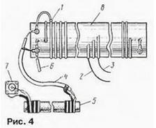
The emitter is also connected to the outlet of the coil (about 16 turns). In Fig. 4 shows two different types of buildings 2 and 3. The thing is. what bandwidth do this the emitter is relatively narrow (because of the marked shortening) and to work in different the ends of the range to vary the point of connection to its matching the spool. To switch, you can use a relay.
Because the fence is not the best "earth", it is possible to eliminate current the braid of the feeding coaxial cable introduced the throttle 5. He wound two wires in the insulation on the core from magnetic antenna radio receiver. The number of turns of the inductor is about 20 (non-critical).
The number of turns of the extension coil was chosen by the author with the reserve for experiments, so you can try to configure it on the 160 meter band.
Note that the length of the GP is close to a quarter wavelength for a range of 40 meters. For it takes only a small lengthening the coil, and the antenna needs to be relatively effective, especially if this range is additionally connect the balances.
Author: JJ7XTV