Sometimes hams trying to squeeze out his radio as much output power, while not paying enough attention to the antenna (especially in wearable radio stations). But the communication range depends on the operation of antenna-feeder path, from how well it is aligned with the output of the transmitter. The field strength indicator gives only approximate information about configuring the antenna. But using an SWR meter can be quite fine-tune the antenna, which will be described below. Scheme SWR meter can be taken from [1].
Simple helical antenna can be made on the frame of polyethylene from television cable stamps of the Republic of Kazakhstan. The workpiece diameter - 9 mm, but you can use cable with a diameter of 7 mm or more. Preparing for the winding is performed as described in [2]. To take the winding wire sew-2 with a diameter of 0,5...0,7 mm length 7...7.5 m. In this antenna was used wire with a diameter of 0.64 mm. Windings are tight, turn to turn. The end of the winding fixed with a strip of adhesive tape or "tape". To connect radio SWR meter and its socket antenna. The switch is moved to the "reflected wave", and in the "Transfer" unrolling first 2-3 turns, and at the end .settings - and by halfway, ensuring minimal readings. It is necessary to avoid having near the antenna metal objects. Tuning accuracy depends on the method of attachment of the wire (the end of the winding) and used this material (duct tape, thread, etc). So the piece of tape is not removed after the final adjustment. Top antenna is wrapped with 1-2 layers of colored adhesive tape ("Scotch") width 10...12 mm. Such isolation has virtually no effect on the SWR of the antenna. The use of a protective sheath of vinyl chloride tube greatly increases the CWS, and she had to give.
Best results can be achieved if the radio station to use a telescopic antenna matching unit. Antenna length ("telescope") to 700 mm At its base it is necessary to insert a brass bushing M5 at the end. Thread length-12mm.

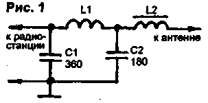
Fig.1
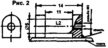
A schematic diagram of a matching device shown in Fig.1. Coil L1 is frameless, wound on a mandrel with a diameter of 6 mm wire sew-2 with a diameter of 0.8 mm and has 9 turns when the length of the winding. 12mm. Coil L2 contains 30 turns of wire wound sew-2 with a diameter of 0.27 mm on the frame Plexiglas performed as depicted in Fig.2.

Fig.2
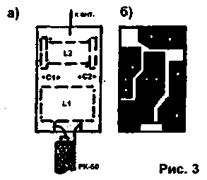
Trimpot core - threaded M3, brand VC, Mr-100, carbonyl iron from the coils SB-9a. Capacitors C1 and C2 - type KD, km. All elements are mounted on a circuit Board from one-sided fiberglass thickness of 1 mm (Fig.3).

Fig.3
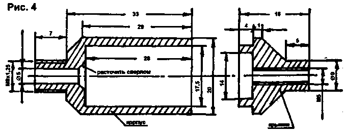
The fee is placed in a cylindrical housing, machined from Plexiglas. The drawing shown in Fig.4. In the cap file is propyl payment.

Fig.4
To configure the antenna need to carve another case with a cutout in the middle to adjust the coils. In the connector SR-50 need to Unscrew the top nut and cut the internal thread MH,25 (you can take and M8). Then the nut screw on the underside of the body with the neck, and insert the Board with a piece of cable RC-50. The braided cable is connected with a split washer, and the Central wire - pin connector SR-50. Connect the connector and a cylindrical body. The telescopic antenna is screwed into the housing cover and a piece of wire connected to the Board. The housing and connect the cover with three screws M2.
The tuning of the antenna lead on the SWR meter. Pinching and spreading the turns of the coil L1, achieve minimum readings in the mode of the reflected wave. Tuning coil L2 clarify the setting. This can be achieved by the CWS S1,1...1,2.
And the last thing to do is to transfer the customized fee matching device in a solid body and to produce the final Assembly.
On correspondence in the letter it is desirable to enclose stamped envelope (residents of Belarus - an envelope with no postage).
Literature
1. Radio,1996, No. 11.
2. Ham, 1999, N5, P. 42.
Author: M. Trotsenko; Publication: N. Bolshakov, rf.atnn.ru


