The task of creating a directional antenna with vertical polarization is not as simple as it seems at first glance. It would seem that turned the conventional elements of the beam (wave channel) vertically, and everything is in order, but the question of attachment of the antenna to the mast. On УSW can be taken bearing the yoke laterally from the mast in the direction of the radiation, but such antenna is unbalanced mechanical and requires for its attachment is very thick and strong mast. Lost the main advantages of vertical antennas - the small size horizontally, the ease and simplicity of installation.
But more on that later, but first you have to stop on the chosen concept of vertical directional antenna. The desire to construct a simple and easy antenna forced to turn to the construction of ZL-Bima, containing only two elements of active power and having a very small size in a length of about L/8 L.../10. At the same time, the Directive gain (directivity) of the antenna is quite significant and equivalent, as indicated in the literature, KND three-element beam with passive elements. This same idea is used in "Swiss squared, is also characterized by a very good value and even greater KND. Therefore, the principle of operation of these antennas deserves careful analysis, and we will now do.

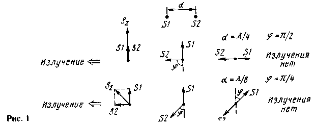
Let's take two hypothetical point emitter S1 and S2 located at a distance d, as shown in Fig. 1 from above. The transmitter power may be divided equally between the emitters, and therefore the amplitude of the fields created by the emitters, will be the same. But the excitement phase emitters must be different to get a directional radiation. First, consider the simplest case, when d = V4, and the power of the emitters is in quadrature, i.e. the phase shift applied to them oscillation is 90°. In the vector diagram (in the middle row, middle) fluctuations emitters depicted by the vectors s1 and s2. The angle f corresponds to an additional 180° phase shift of the oscillations. We agree also, phase foray (lag phase) in the propagation of waves at some distance to take into account the rotation of the vector clockwise by a corresponding angle. For example, the wave traveled a quarter wave acquires a phase foray 90°.
Let us consider the radiation system to the right, and the phase of the waves will be measured directly at the emitter S2 (with further propagation to the right from both waves of the two emitters will acquire the same phase shift, and the phase relationship between the vibrations will not change). The corresponding vector diagram shown in the middle row on the right. Oscillation s2 will not change, and the oscillation s1 acquire phase foray 90° passing the path of L/4. As a result of the wave will be and antiphase radiation in this way will not. In the propagation of waves in the left side of the emitters vector s1 will remain in the same position, and the vector s2 rotates 90° clockwise, as a wave from the emitter s2 on the path to L/4. Vector diagram of oscillations near the emitter s1 shown in Fig.1 in the middle row on the left. It is seen that the waves from the emitters S1 and S2 are added in phase and total oscillation becomes double the amplitude.
In exactly the same way you can find the radiation field in other directions. For a more visual representation can be considered that in Fig.1, the top plan view of two whip antennas S1 and S2. Such a system of two pins will have a radiation pattern close to the cardioid. The maximum radiation is directed to the left, and zero radiation to the right. In lateral directions (upwards and downwards in the figure), the system also will radiate, and quite significantly, because in these areas will develop two quadrature wave. Slightly increase the sharpness of directivity diagram is possible, having emitters S1 and S2 are closer to each other, for example, at a distance L/8. Vector diagram for this case is shown in the bottom row in Fig. 1.
Assuming that the radiation is to the right, as before, should be absent, as defined phase shift of the oscillations emitters. It needs to be SN/4 or 135°, as shown in the vector diagram in the center of the bottom row. Then right in the radiation vector fluctuations s1 is rotated by the angle p/4 or 45° , and will be in opposite phase with the vector s2 (see vector diagram in the bottom row right). When the same radiation to the left side of the vector s1 and s2 will be out of phase, and will be in quadrature, and the resulting amplitude of the field will not be doubled, as in the previous case, and will only 1,41 times more fields of each of the emitters (the vector diagram on the left). Radiation side will be less, as these areas develop close to anti-phase field. The distance between emitters can be done even less, but for unidirectional radiation angle complementary to the phase shift in the emitters to antiphase, must satisfy the condition: f = 2пd/L, i.e. must also decrease.
We should not think that the effectiveness of "short" antenna with a small d and almost antiphase emitters is less than the efficiency of the "full-size" with a distance d = L/4. If losses in the elements can be neglected, then all the power supplied to the antenna system needs to be transmitted, and the fields of the two antennas should be the same (neglecting the small difference in the directional diagram). But the currents in the elements of the "short" antenna to create the same fields are large, and if the losses in the elements, they also increase because of large currents.
Anti-phase currents in the elements of the "short" antenna such antiphase currents in the coil and the capacitor of the parallel resonant circuit, the amplitude of which is proportional to the quality factor. Similarly, by shortening the distance between the vibrators and the approach of the currents in them to anti-phase equivalent increases the quality factor of the antenna system, and thus decreases its working band of frequencies. This is the fee for a size reduction. But when the distance between the vibrators L/8 L.../10 the increase of losses in the elements and is equivalent to q does not exceed 1,4...2 times and it pays for itself by reducing the size of the antenna, and confirmed by long practice design ZL-Bima.

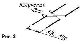
One of the most simple designs ZL-beam shown in Fig.2. It contains two split half-wave vibrator (and often use the loopback vibrators), United air line intersecting wires. Since the velocity factor of the wave in air line close to unity, then the system power points in "X-X" phase shift of the oscillations in the vibrators just corresponds to the above formula. A more accurate phrasing of the elements is achieved by changing (selection) of their length. This changes the resonant frequency of the element and, just like any oscillating circuit in accordance with its phase-frequency characteristics, phase fluctuations in it.
Strictly speaking, the power supply can be provided even by the middle line, and the phasing elements to implement in this way: one element slightly shortened, and the other to slightly increase. The detuning of the elements becomes very small, since the required phase shift in each element is only f/2. Directivity ZL-beam in the horizontal plane (azimuth) is noticeably narrowed because the vibrators do not emit sideways. In the vertical plane chart is somewhat wider. This antenna is very good as a small-size directional antenna with horizontal polarization. According to numerous reports in the literature of its KND reaches 4 dB relative to a dipole or 6 dB relative to isotropic (Omni-directional) of the radiator.
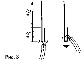
For obvious constructive reasons to have vibrators ZL-Bima vertically is not very easy, in addition, problems with wiring the line power. In view of these difficulties, the author's thoughts turned to a more appropriate vertical emitters, which could be placed at a small distance from each other, in accordance with the ideology ZL-Bima. One of these emitters is J-antenna, two variants which differ only in the way of harmonizing with the feeder shown in Fig.3.

J-antenna is a half-wave vertical dipole, fed from the lower end. At the end of the impedance of the vibrator is very high and reaches a few shortfall in full accordance with Ohm's law - because the current here is small, and the voltage is large. To align with the low resistance of the cable serves as a quarter-wave two-wire line. In the first embodiment (to the left in Fig.3) its characteristic impedance should be equal to the geometric mean between the resistances of the vibrator and cable, i.e. something in the region of 300...600 Ohms.
Exact matching can be achieved by modifying characteristic impedance of the line (almost - the distance between conductors). It's not very convenient, so the second option J-antenna (on the right in Fig.3) in many ways better. Here the conductors of a quarter wave line just closed at the lower end, and the point of zero potential to ground wire of any length, to connect with any "mass", for example, the roof of the house or car, which is convenient constructively, but you generally will not attach. Power is supplied to the line autotransformers, at points "X-X" located at a certain height above the short-circuited end of the line. With any cable antenna can be easily reconciled simply by moving the feed point of the "X-X". Wave resistance of a two-wire line in this embodiment is of no special importance.
Further the thinking was that if two J-directional antenna in the system will be located near, is it possible to use for their food and agreeing a common two-wire line? Because the voltage on the conductors of the open end of the line-of-phase, which is required to power the two closely spaced vibrators! Well, the necessary phase shift of the oscillations in the vibrators +f/2-f/2 can be obtained by changing their length - shortening one and lengthening the other. It remains to decide how to connect the ends of half-wave dipoles, spaced at L/8, with the ends of the two-wire line located nearby. It wasn't hard at the ends of the vibrators current is small, they emit almost no, so nothing bad will happen, if the ends of the vibrators to bend towards each other and directly connected to the ends of the line. All turned out incredibly simple, so that any doubt, a earns? Needed was an experiment.
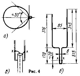
No sooner said than done, antenna to the frequency of 430 MHz (a wavelength of 70 cm) was bent out of a single sheet of copper wire with a diameter of 1.7 mm., a thumbnail with size, refined in the process of the experiments shown in Fig.4 b).

Power cable with a characteristic impedance of 50 Ohms joined as shown in Fig.4). Contacts at the point of supply "X-X" is useful to make moving to find the position of these points at a minimum SWR. Unfortunately, the CWS was trying on nothing, and the provision of power points have been matched to the maximum field of the antenna in the main direction. The field indicator was used homemade, consisting of a dipole antenna, a diode detector and the measuring head 50 μa. The signal source served as the measuring generator with an output impedance of 50 Ohms and the attenuator in 1 dB increments. The original antenna was fixed in desktop tisochkami for bottom base two-wire line, then was made primitive swivel stand. Although the measurements were carried out in an unequipped room and don't aspire to high accuracy, the antenna is fully met expectations!
First, the antenna worked, and gave a unidirectional radiation in the short side of the vibrator. Secondly, when compared with the half-wave dipole located in the same location and connected to the same cable, attenuator generator had to enter by 4 dB to get the same signal on the indicator field. This allows to estimate the directivity of the antenna the same numeral. Directivity in the vertical plane (plane of vibration) is shown in Fig.4 and, in General, fully correspond to the same two-element diagrams of Bima. In the horizontal plane chart is the same, but slightly wider. Interestingly, the adjustment of the length of the elements can achieve a complete absence of posterior lobe (in any case, the indicator field is not found), but the KND was somewhat at a fraction of a decibel, less than in the configuration of the antenna for maximum directivity. Finally, some practical considerations in design implementation of the proposed antenna.
For increasing the mechanical strength can be set insulator at the ends of the two-wire line, in the region of its bend and transition to the conductors of the vibrator. The insulator shall be of good quality, since there is a voltage antinode. The curves do not necessarily at a right angle, the "shoulders" of the antenna can be tilted. Moreover, it seems to the author that the "shoulders" is not particularly critical - they can be located slightly above and slightly below. Much more important to observe the full length of the wires from the bottom base two-wire line to the upper end of the vibrator. It should be about 0,73 L. for short vibrator (Director) and about to 0.77 L for long (reflector). With the increasing diameter of the conductors (tubes), made antenna, their length decreases. The velocity factor of the "thick" of vibrators can be found in the literature on the antennas. Note also that there is no need to produce vibrators and the pair of tubes of the same diameter. The antenna will get stronger and will better withstand wind loads, if the two-wire line to run from tubes of larger diameter, and vibrators to make relatively thin. For convenience of adjustment vibrators useful to equip the "Shinigami upper end telescopically digemari in the main pipe, as the shortening of vibrators clippers, as did the author, is fraught with irreversible consequences - extend after this vibrator is possible only with the help of a soldering iron.
Author: Vladimir Polyakov (RA3AAE), Moscow; Publication: N. Bolshakov, rf.atnn.ru


