


")

Ham radio operators conducting experiments with television receiving antennas, it will be easier to realize their dreams, if they have a permanent set of typical the antenna elements - a single structural basis. This set here and offered. The author also considers several variants of design of antennas.
Applying a single structural basis, i.e. the same materials and basic design elements, it is possible to make an antenna device of a different type, the purpose and the working frequency band. This will allow them to quickly collect, modify, constructively, to measure and compare different electrical parameters.
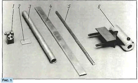
Elements (workpiece materials) of the proposed single structural basis antennas, working mainly in the UHF range, depicted in Fig. 1. It contains block 1 with dimensions 44x22x14 mm aluminum, the insulator 2 with the size 30x24 mm and thickness 1…4 mm of fiberglass pipe 3 with an outer diameter of 14… 18 mm aluminum (for example, ski pole), lane 4 aluminum width 22 and a thickness of 2.. 6 mm rod diameter 5 3,57…8 mm of aluminium conductors electrical cable (1) and the fixing unit 6. The latter consists of dural sleeve, angle steel, fasteners and provides the installation of the antenna on the mast or vertical bracket with a diameter of 12 to 50 mm. Elements can be modified depending on the specific requirements of the design: to make threaded or unthreaded holes in the Shoe or the insulator, to compress (flatten) the ends of the rod and make the screw holes, etc.
Consider the features of different types of antennas built with the constructive elements of the basis, for example adoptive TV devices.
In Fig. 2 shows a double zigzag antenna (DZA) UHF. Her power the elements of the upper 1 and lower crosshead 9 from the pipe and 2 of jumper strips the thickness of 6 mm., the Jumper is located on the line of zero potential and does not affect the electrical parameters DZA. Active vibrator 4. broadband loop the reflector 5 with a shunt 6 (2] from rod and bridge 2 connected to the traverse 1 and 9 four mounting pads 8. For this purpose, in the stocks before Assembly made threaded M4 holes (MH-M6) Active vibrator 4 is protected from strain insulator 7.
The upper cross member 1 is fixed by a screw 11 in the mounting Assembly. Therefore, excluded as the wall deformation during clamping yoke and beam loss when loosening the screw. For electrical installation DZA cable used RK75-2-13. the petals of tinned copper wire with a diameter of 1.4… 1.7 mm and brackets of tinned copper or aluminum wire of the same diameter. The cable installed the contacts in the insulator 3. These same contacts plug screw cable the reduction. The immobility of lead-in cable at the connection pad provides 10. The size of the vibrators 4 and 5 vertically between the axes of the mounting holes is equal to 322 mm., the Distance between the vibrators - about 100 mm Weight DZA without knot fixing -0,5 kg Mass of the mount - 0.3 kg.
In Fig. 3 shows antenna "wave channel" (AVK) for UHF. Vibrators AVC made from rod and the shape of the folded dipole, but those is only active vibrator 1. since the rupture of the lower conductor there insulator 2. Each of the passive radiators are closed by the spacer 3 from streaks. Material vibrators work in tension and compression, which allows to withstand heavy loads in the vertical plane, the cause of which can be birds. With this structure, vibrators bandwidth and efficiency antenna increases due to the greater surface conductors.
In AVK used band balun device (DSU) [3]. consisting of a quarter-wave short-circuited symmetrical lines 5. quarter-wave open unbalanced line 4 and part of the lead-in cable located on opposite branches symmetrical lines.
Cable RK75-4-11 cut and secured with wire ties in the quarter-wave line 5. The twisted ends of the wire connected screw contacts on the insulator 2. Copper ends clamped between the steel washers to exclude education electrogalvanic pair of copper-aluminum. The length of the vibrators - such (from left to right in Fig. 3): 240.250.254.264,and 348 286 mm Distance between them - 73. 90. 90. 78. 151 mm.
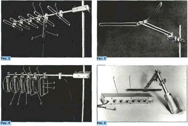
Multi-element antenna (MRA) for UHF shown in Fig. 4. In each of loop vibrators MRA has a stiffener of slotted on one side stripes located on the line of zero potential and perform another function. In the active vibrator 1 it (2) serves as a quarter-wave line band balun transformer (DTR) (4). the reflector element 3 stiffness 4 performs the functions of an electrical extension cord reflector and controller its natural frequencies by moving adjusting the looper 5. In the Director of 7 the stiffener 8 is used to change the natural frequencies Director looper 9. The required reduction of the perimeter of Directors provided the octagonal shape of the conductors. All the stiffening elements have a length of 145 mm. Electrical installation cable is made RK75-2-13. Output impedance MPA is equal to 15…20 Ohms. therefore, as a quarter-wave transformer resistances 6 in DST used two parallel cable cut to obtain the wave the resistance of a quarter-wave transformer 37.5 Ohms. The perimeter of the reflector and active vibrator - 536 mm perimeter of Directors - 448 mm Distance between elements 73 and 67. 67, 62,101 mm Weight MPA without mount - 0.8 kg.
DZA, AVK and MRA allow the change in the number of vibrators and the distances between them without disassembly of antennas and without disconnecting the cables.
The examples do not exhaust g of the possibilities of application of the proposed constructive basis. In Fig. 5 shows sebenarnya antenna on the basis of split vibrator. She works in intervals of 6-12 21-40 and television the channels.
The angle in the horizontal plane between the halves of the vibrator equal to 120°. Length each half of the vibrator - 360 mm Length quarter-wave symmetric lines, formed by two pipes with a diameter of 16 mm is equal to 390 mm., the Distance between the axes of pipes 60 mm.
Cable RK75-4-11, padded inside pipes, together with a symmetric line form DSU (3]. The cut length of the cable in the left pipe - 240 mm.
Assembling each of the antennas multivariate. For example, in the reflector DZA (Fig. 2) applied shunted the folded dipole, although it is possible as removal of the reflector and the use of his flat design with linear horizontal vibrators from rod or strip.
Another example of the same DZA. Vertical jumper 2 in Fig. 2. serving as part of the power of the "skeleton" design made of strips of a thickness 6 mm If it is made of a material thickness of 2 mm, the rigidity can be increased, and a lot lower in comparison with the original version, using two identical the jumpers. One of them set as the jumper 2. and the second is attached to opposite planes pads parallel to the first jumper. Thus there is enough stiffener instead of flat.
Installation on vibrators MPA (Fig. 4) shunts, similar to the shunt in the reflector 6 DZA (Fig. 2). extends the working range MPA in the direction of low frequencies, and the reduction of the perimeter loop vibrators due to the change in shape at constant the coordinates of the mounting holes operating range shifts to the region of high of frequencies.
Described above are designed for outdoor installation. Extending constructive basis with plastic or wooden dowel and applying prefabricated used for the pads, you can collect one of the modifications duopoloy antenna UHF [3. 5], designed for rooms.
Select the type of antenna in the absence of measuring devices is reduced to the evaluation test table as provided by the antenna. For comparative quantitative evaluation of the results apply speed attenuator 1 [6]. it is shown in Fig. 6. The normalized impedance attenuator -75 Ohms. ultimate fade - 63 dB. the discreteness of -1 dB. number of steps - 6. Each stage is placed in a separate shielding enclosure slot. Electric the parameters collected antennas is compared with the parameters of the auxiliary antenna 2 on Fig. 6. The measurements with the step attenuator used as a TV a threshold device. In this regard, there is no need to open the TV and to interfere in its chain. Objective indicator threshold signal is the change in the synchronization scan.
Literature
Author: A. Trifonov, St. Petersburg