In recent years, the interest in Amateur radio 2-meter range is constantly growing due to the increasing number of FM repeaters and, consequently, to improve conditions for the development of mobile communication networks of different BBS and portals, including Internet access and satellite transponder. Increase the activity contributes to the resolution of March 1, 1998 to work on УSW novice radio Amateurs.
When working on the 2-meter range using antennas with vertical polarization (mainly for mobile communication and working through repeaters) and horizontal. Thus it is desirable to have an antenna with a circular radiation pattern in horizontal and vertical planes. The latter is very important when working via satellite (AES) repeaters. For these purposes, as a rule, apply multiple antennas, which reduces the efficiency in work subject to far unstable passing on the 2-meter range.
The author managed to solve this problem by introducing antenna with almost spherical. In this case, the antenna can radiate and, accordingly, to receive electromagnetic waves in both vertical and horizontal polarization.
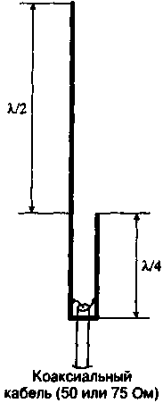
The basis for the design is a popular J-antenna (Fig. 1). It is a vertical dipole, fed with the lower end using a short-circuited quarter-wave line. As is known [1], this antenna works only with vertical polarization and has a pie chart in a horizontal plane with a deep minimum in the vertical direction.

Fig.1
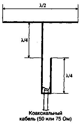
The author has proposed a change in the form of a vertical radiator of the antenna by twisting the dipole in half at 90°. In this case the horizontal part of the dipole in the first version consisted of two opposite elements of length L/l each (Fig.2) and was first described in the book "Info" No. 4/1990, pp. 42,43.

Fig.2
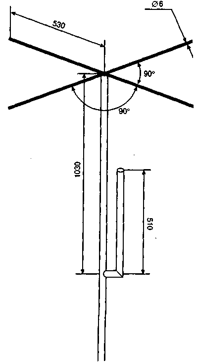
In the latter modification, the author suggested to perform the horizontal part of the radiator 4 are mutually perpendicular line segments of length l/4 having electrical contact with the vertical part of the radiator (Fig.H). The antenna design is easy to manufacture and easily repeatable even for novice hobbyists. The vertical part of the antenna is made of a tube with a diameter of 32 mm Material - bronze, brass, copper, and aluminum alloys while ensuring reliable electrical contact of all parts of the antenna and matching device (soldering or welding). Horizontal cross-shaped part made of a rod or tube of 6 mm in diameter (material - similar applied with a 32 mm diameter tube).

Fig.3
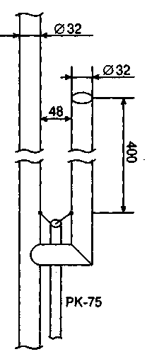
This structure also retains the advantage of the J-antenna, in which the lower end of the short-circuited quarter-wave line may be grounded, for example, is electrically connected to a grounded mast and in this case the whole antenna can serve as a good lightning rod. The setting is in the selection connections power cable to the matching line (Fig.4) for minimum SWR. The author used the RC-75. but you can use a feeder with a characteristic impedance of 50 Ohms. When indicated in Fig.3, 4 sizes and 75 ω feeder VSWR=1.0 to close at 145.5 MHz.

Fig.4
The antenna is mounted on a grounded metal mast at a height of 7 m above the ground, but you can use the mast of any material and design. Extraneous conductive objects should be removed from the horizontal elements is more than 2 meters. With a corresponding change in the geometric dimensions of this antenna can be built for other УSW ranges.
This antenna works from the author since 1983. Showed good results for all types of passage, and also with the links via Amateur satellites in the area of their visibility and no failure signal "over the head". During "Field day 2000" on the basis UT0H an experiment was conducted, during which the signals of my lighthouse, which was used in the described antenna, took on the antenna in both vertical and horizontal polarization with about the same volume.
From the editors. In Fig.1 and 4 show two variants of connection of the cable to the matching line. In the first case (Fig. 1) the metal core is welded to the conductor line connected to the emitter, as in the original (Fig.4) - on the contrary. Both have the same effect, although in the publication" the more common way of connecting the cable depicted in Fig.1.
Literature
1. Bieńkowski 3., Lipinski, E. Amateur antenna short and ultrashort waves: TRANS. with Pol./Edited by O. P. Frolov. - M.: Radio and communications, 1983. 480 p., ill. - (Mass radio library; Vol. 1052).
Author: Anatoly Kalashnik (UT5VD), S. Protopopescu, Alexandrovsky district, Kirovograd region; Publication: N. Bolshakov, rf.atnn.ru


