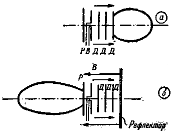
Antenna with reverse radiation differs little from the antenna type wave channel having one or more Directors, the active vibrator to the reflector. If modifications of a conventional antenna wave channel in the antenna with reverse radiation ahead of the first Director on the distance l is set to about 1/4 flat reflector wall (Fig. 1).

Fig. 1, and the radiation pattern of the antenna wave channel;
b - directivity antenna with reverse radiation
(D Directors, vibrator, R - reflector).
The energy supplied to the active vibrator antenna is radiated in the direction of the Directors, before reaching the reflector wall is reflected from it (as a reflex wall in length and has more To explicit inductive), comes again to the vibrators antenna, inducing them additional EMF
Due to this, there is also a considerable narrowing of the lobe radiation and rotate it 180° (that is, the energy is concentrated in a narrow direction).
In the above literature it is reported that adjoined to the ordinary wave channel of the reflector wall, you can achieve a win in the backward radiation of about 5.2 dB at 0.5 in comparison with the antenna wave channel, the angle of radiation is narrowed from 41° to 24.5°, side and rear radiation are much smaller.
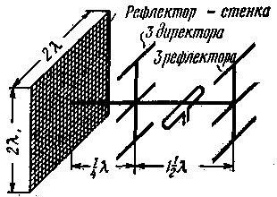
The horizontally polarized antenna with a length of 1.5 l with the reflector wall (dimensions 2lx2l) and comprising one of the active vibrator, three Directors and three reflectors disposed one above the other (Fig. 2), the gain of 14.5 dB at 0.5; the angle of radiation in the horizontal plane is 25.5°, vertical - 28°.
The reflector wall may be made of sheet metal or of densely intertwined mesh (the latter is better because of the smaller sail).

Fig. 2. General view of the antenna with the reflector wall.
The same result can be obtained when using simple antennas wave channel from one of the active vibrator, one Director and one reflector. It is proposed to build antennas with reverse light with a win from 10 to 25 dB in cases when the antenna wave channel is too cumbersome, and a parabolic antenna is not cost-effective to apply.
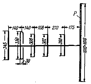
In Fig. 3 gives a relatively simple antenna for the range of 420 MHz, at which measurements were taken, fully confirmed the above-mentioned characteristics of the antenna with reverse light. This antenna without special adjustment gives a gain in 4-4,5 dB more than the usual wave channel.

Fig. 3. Antenna with reverse light to 425 MHz
the reflector wall R made of metal mesh,
the distance between the wires is 10 mm; the diameter of the tubes all
vibrators - 8 mm).
I would like to have our Amateurs began to experiment widely with such antennas, as only with a good antenna can achieve far ties confident and good television reception centres located outside the coverage area.
Author: K. Fechtel (UB5WN), Kyiv; Publication: N. Bolshakov, rf.atnn.ru


