Automatic process antenna - wideband directional antenna operating in tenfold and a broader range of wavelengths. The coefficient of amplification of the antenna is equivalent to three-up antenna "wave channel". Can be used to receive signals from the multi-program telecentres with any combination of channels meter and decimeter waves (channels 1 to 41).
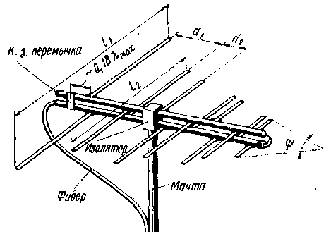
One of the simplest antenna is shown in Fig.1. The antenna consists of a series of parallel vibrators connected to two-wire line with consistent polarity of power points vibrators. The length of the vibrators and the distance between them decreases exponentially in the direction to the points of connection of the feeder. Behind the longest vibrator set short-circuiting jumper that improves the coordination of the antenna with feeder and providing balancing.

The cable is passed inside one of the tubes of a two-wire line and solder from the side of the shortest of the vibrator, as shown in Fig.1.
Characteristics of the antenna depend on the denominator exponentially t, characterizing the rate of decrease of the lengths of the vibrators and the distances between them, and the angle f at the vertex of the triangle which is inscribed in the vibrators. The closer t to one and less than f, the higher the antenna gain, but increase its size and weight. In practice usually take t =0.8 to 0.9 and f=30-40°, which allows to obtain a sufficiently high gain with relatively small dimensions and weight.
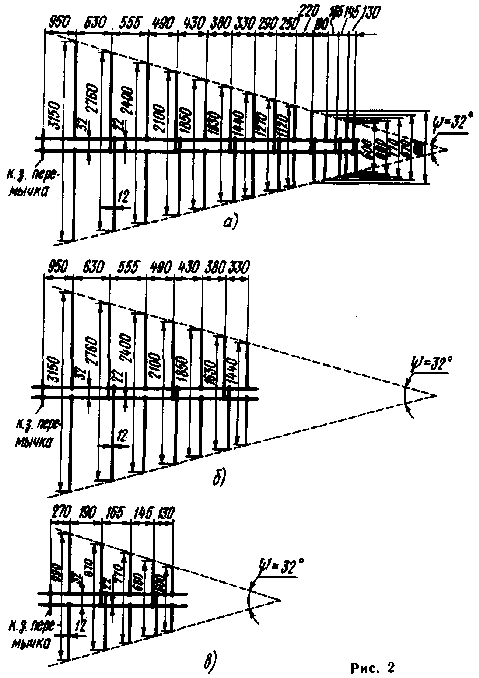
When selected t and f antenna dimensions can be defined graphically on the basis of Lmax and Lmin - minimum and maximum wavelength of the operational frequency band. First, you must determine the length l1 of the first (largest) of the vibrator, which should be 0,55 Lmax, then draw an isosceles triangle with base equal to the length of the first vibrator in a smaller scale (such as 1 : 20 or 1 : 50), and a selected angle f at the top. In the future, all drawings and calculations should be performed with consideration of the same scale. The second vibrator have a distance d1 = (0,15-0,18) Lmax. The length l2 is equal to the length of a line drawn parallel to the base at a distance ri.

The third vibrator have a distance d2=d1т from the second, and the length l3 is equal to the length of a line segment, held at this distance from the second vibrator. Likewise is determined by the length of the fourth vibrator, located at a distance d3=d2т third, and so on, is the vibrator, which length will be less than 0,45 Lmin.
In Fig.2,and shows the size of the antenna for channels 1 to 12, in Fig.2,b - channels 1 through 5 in Fig.2,in the canals 6-12. Using the described technique, it is possible to calculate the antenna on channels 1 to 41, as well as for other desired frequency band.
The antenna gain of 6-7 dB, the level of side lobes is from -12 to -14 dB, IPM is more than 0.5. The diameter of the tubes two-wire line 22 mm, the distance between the centers 32 mm, the diameter of the vibrators 12 - 14 mm Cable with a characteristic impedance of 75 Ohms.
The radio Amateur's Handbook-designer
Addition from Nikolay Bolshakov
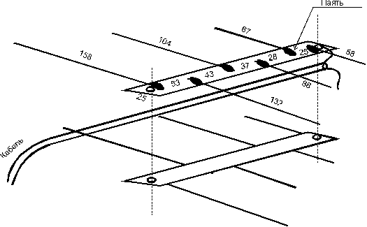
Personally, I have collected several of these antennas for UHF television. As the material were used segments of copper wire with a diameter of 0.8 - 1.5 mm and two-sided glass plate of fiberglass. Vibrators of the wire are soldered to the plates. The design is very simple and easily repeatable. The dimensions of the antenna for the range of 400-850 MHz is shown in the figure below. On plate size h mm solder vibrators wire (both parts are exactly the same), the bottom half is rotated 180 degrees about the axis. Both plates are connected through the sleeve (5-10 mm) screws through the holes at the ends of the plates. The screws must be isolated from the foil. The cable is located between the plates.

The dimensions of the antenna for the range of 850-950 MHz (cordless phones)
Table 1 Room
itemOverall length
vibrators, mm The distance from
previous
element, mm The distance from
the end of the boom, mm 5176 044 4141 5195 3113 40135 290 32168 172 26194
Theoretically parameters:
- The gain is 8.3 DB,
- An impedance of 60 Ohm.
Publication: N. Bolshakov, rf.atnn.ru


