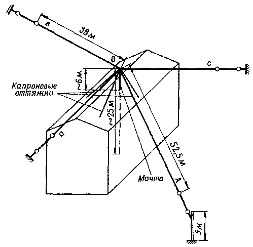
In Fig. 1 shows the antenna that I use for work on a range of 160 m. It consists of a sloping radiator and three balances a, b, c, stretched parallel to the ground.

Fig. 1
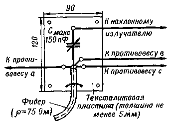
Nourish the unbalanced antenna coaxial cable with a characteristic impedance of 75 Ohms. The center conductor is connected to the variable capacitor C1 (Fig. 2) the matching device, which is placed in a sealed box.

Fig. 2
To configure the antenna, you need an SWR meter. First of all balances must to be disabled. Then the two of them, for example a and C, connect a feeder with a characteristic impedance of 75 Ohms and connected to the transmitter, determine the CWS in the middle and on the edges of the range. If the SWR is high, it is necessary to adjust the balances, changing their geometrical dimensions. A similar operation was doing and with a third counterweight, first disable any of the previous ones. After setting all of their balances is connected to the braid of the cable and adjust the tilting radiator. By changing the capacitance of the variable capacitor, achieve minimum SWR in the middle of the range.
In the original SWR of the antenna in the middle of the range was equal to 1.3, on the edges of the range - not more than 1.6.
Author: V. Starostin (UA3PFC), Tula; Publication: www.cxem.net


