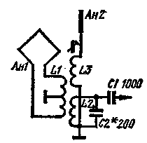
The inclusion of antennas according to the scheme shown in the figure, allows you to get a good cardioid setup. The phase shift EMF framework at an angle close to 90°, is setting circuit L2C2 in resonance.

So when the detuning circuit is the angle of phase shift was close to 90°, the factor of the circuit should not be too large.
In the range of 3.5 MHz, the frame may be made in the form of widespread designs of the split ring, inside of which is wound 6 turns of wire. Coils L1, L2 and L3 are wound wire sew-1 0,14 on a standard frame with a diameter of 4 mm with a ferrite bead attached to the end. Coil L1 contains two windings 7 turns, L2 - 50 turns, L3 - 20-25 turns. The capacitance of the capacitor C2 are selected such as to obtain resonance at the middle frequency of the operating range.
Balancing beam coil L1 is wound is strictly symmetrical. Configuring the directivity confined to a small selection of the number of turns of the coil L3.
Similarly can be made antenna on 28 MHz.
Author: A. Partin (UV9CO), Sverdlovsk; Publication: N. Bolshakov, rf.atnn.ru


