Remote matching device proposed by the author of this article, allows you to place the antenna in the form of a long wire (beam) free from surrounding objects space. It is quite versatile and can be applied, with some modifications, to various types of antennas.
The dream of the shortwave is to have a separate antenna for each Amateur range. But it is not always feasible, especially in a big city. Often have to choose one of the tradeoffs multiband wire antennas. At the same time to work on the air ideal antenna length about 41 m fed from one end. To coordinate such an antenna with low output resistance transmitter by using a simple matching devices, but they have one drawback. Agree that it is not very convenient in the management of matching device located on the balcony (the balcony) and even on the windowsill, if the workplace ham is not near the window, which opened the power wire antenna.
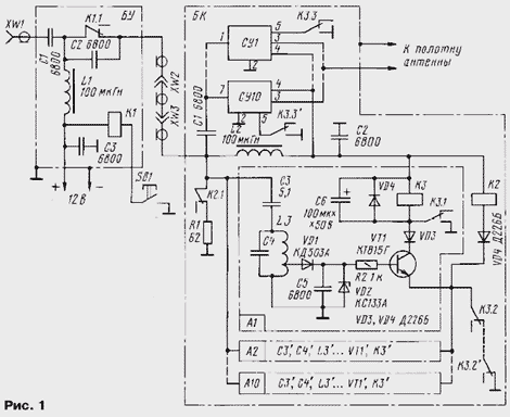
Proposed in Fig. 1 a diagram of the automatic switching-matching device (AKSU) allows you to place the antenna in free space, getting rid of these drawbacks. Antenna power and control AKSU carried over a coaxial cable (50 Ohm). The device consists of blocks control (control unit) and switching (Bq). BOO is on the transceiver. It contains the relays K1 and the reset button SВ1. BC is located directly beside the antennas. It contains a matching circuit for each Amateur band and the scheme of automatic selection of the required matching circuit.

Operates a switching device as follows. When voltage is applied power +12 V on BU it through the filter L1C3, normally closed contacts of relay K1 (BU), coaxial cable and filter L2C2 arrives in BC. As in the original normally closed contacts K3.2 all relay K3 cell selection A1 - a10 connected in series, relay K2. Your contacts it connects to the cable equivalent of the load R1. This is necessary in order for the output stage the transceiver for the period of determination AKSU desired band was included on a matched load. In parallel, the equivalent of the incorporated cell selection signal A1 - a10, representing the simplest detector receivers, control transistor VT1 and VT1'
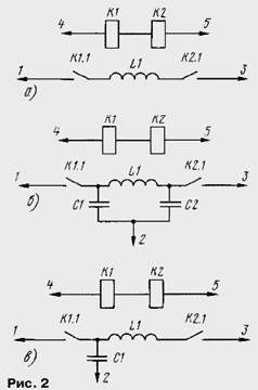
When the radio is powered on transmission activated from the cells, the frequency settings which coincides with a selected range of the transceiver, for example A1. Relay K3 through contacts K3.1 self-locking, remaining in an on state, and after removing signal transmitter. Simultaneously opens the contacts K3.2, making impossible to activate another cell and disabling the dummy load. Third contacts K3.3 includes corresponding matching device (Fig. 2), for example SS1, in the antenna circuit. The scheme in Fig. 2,and used in the ranges of 160, 80 and 30 meters, in Fig. 2,b is in the range of 40, 20, 17 m; Fig. 2,in - the ranges of 15, 12, 11 and 10. Constructive data matching circuits for each range are shown in table. 1.

When changing the range of the transceiver AKSU should be returned to its original state, clicking on SВ1 on the block BA. While short-term stress is removed power block Bq. To improve the reliability of the whole system enabling matching device should be performed at low power transceiver - 5...10 watts.
Table 1
Range, m The length of the winding, mm The diameter of the frame, mm The number of turns C1, pF S 2, pF Setting 160 60 40 20 - - By changing the length and number of turns 80 60 40 15 - - - " - 30 50 40 10 - - - " - 40 40 34 14 1000 120 Selection C2 20 45 34 8 1000 100 - " - 17 45 34 7 750 75 - " - 15 45 34 6 510 51 The selection of C1, the length L1 12 45 34 6 390 - - " - 11 45 34 6 300 - - " - 10 45 34 6 270 - - " -Note. All coils are wound wire sew-2 2.0 mm.
In table. 2 shows contours L3С4 - L3С4 cell selection A1 - a10. When the implementation of the coils exactly with the description of the circuits will be tuned to the appropriate range. But in closely spaced bands 12, 11 and 10 m require more extensive setup. She is trimmer the load capacitance of 30 pF belonging to the General capacity C4. Capacity capacitor C3 should not be more 5,1 pF. If such a cell capacity selection does not operate, the more accurately adjust the outline or reduce L3C4 the base resistance of the resistor R2 (but not less than 100 Ohms).
Table 2
Range, m The number of turns Wire The challenge(counting from the cold end of the coil) Capacitance C4 Note 160 68 Sew-2 0,2 10 360 The bulk of the resistor is 100 kω 2 80 38 - " - 7 300 - " - 40 22 Sew-0,3 5 270 The bulk of the resistor is 100 kω 1 30 17 - " - 4 240 - " - 20 17 Sew-0,4 4 120 Ordinary on the resistor is 100 kω 1 17 17 - " - 4 100 - " - 15 15 - " - 3 91 - " - 12 15 - " - 3 91 - " - 11 15 - " - 3 36 - " - 10 15 - " - 3 30 - " -The establishment of matching circuits (Fig. 2) also should be carried out at low power transceiver (5...10 watts). It is very convenient to use tension indicator field. The selection of containers N-contours, stretching or compression of the turns of the coils should achieve maximum readings. Only after that you can apply for a matching device full power and measure The CWS system. If the SWR on any band will exceed 2, make an additional adjustment to the contours of the agreement, using SWR meter or measuring bridge.
To BA and BC are used relays K1, K2, K3 - K3' type -22 (passport RF4.500.131). For switching the matching circuits are applied relay PCM-1 (passport 10.171.81.50), connected in series. Load R1 recruited from ten resistors type MLT-2 620 Ohms, connected in parallel. Coil to BA L1 and L2 in BC standard chokes, rated current 1 A. They can produce and independently, winding 60 turns of wire sew-0.8 mm 2 round round ferrite rod with diameter of 8 mm and a length of 80 mm from the antenna transistor receiver.
The switching unit is made of two boards of foiled fiberglass. The installation was carried out at the place of installation of the details on the patch. On the same Board collected matching device along with their changeover relay, on the other collected cell breeding ranges. After the final adjustment block hermetically sealed.
AKSU operated transceiver with an output of 100 watts. When the use of high current relays and the corresponding mounting device power supplied thereto, can be improved.
The principle laid down in AKSU, can be used with other types of antennas, using just the corresponding matching circuit.
It is desirable to use a counterweight length 41 m or produce the frame ground matching the electronic device on the ground at the place of installation of the antenna.
Author: Igor Grigoriev (RK3ZK)


