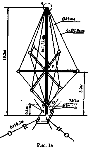
Being in Essentuki (UY5AP/UA6H), I met with George - UA6HVX who had installed the antenna, similar UW4HW, a height of 20 m. the Antenna worked fine on 3.5 MHz and not bad at 1.8 MHz! Then I redid my GP on 7 MHz in such an antenna, but with the height of 10.2 m Fig.1. The antenna works since 1986, hundreds of DX QSOs on different bands. 3.5 MHz JA 569 give when the output power of 120W. On all other ranges of almost all DX, which I hear. When the output power of 0.5 W a QSO with NM7G on 14 MHz, which is appreciated by my signals at 449. SWR range: 3.5 MHz - 1,2,7 MHz - 1,2; 10 MHz - 1,2; 14 MHz To 1.1; 21 MHz - 1,3; 28 MHz to 1.2.
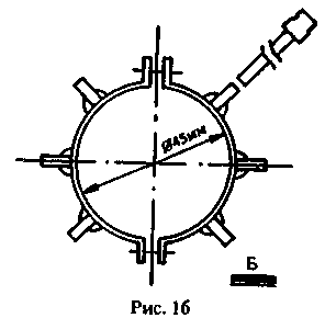
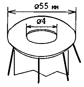
The antenna is stretched two tiers of braces. Horizontal spacers made of metal tubing with an internal diameter of 10 mm, which are pinned on the bolts 10 mm, welded heads to the bracket (position B). On the other end of the tubing reinforced roller insulators to which are attached wires. In the upper part of the mast reinforced insert is equal to the internal diameter of the mast with a Central hole for M4. Here is screwed puck from bilateral fiberglass thickness 1,5 - 2 mm (position A).

Both foil side of the washer need to solder. In seven of the holes of the washers are inserted the ends of the wires and soldered thereto. Washer M4 screws are screwed. Thus, on top of the mast is obtained and the mechanical and electrical contact wires of the antenna.

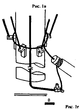
The seventh wire is needed to eliminate bad contacts in the articulation of the mast and along the mast, connected to the counterweight, and a braided cable. In the bottom of the antenna 6 wires threaded into the holes of the l-shaped insulators (position B) and are interconnected in the form of a ring.

These insulators are attached to the mast with electrical tape. To this ring is soldered lived cable. Braid of the cable to the counterweight, which are connected in pairs to the four bolts on metal glides antenna, located on the flat roof.
Thus, all connections of the working part of the antenna is soldered and not affected by climatic influences, which is very important! If another connect four counterweight length of 20.4 m, the antenna will work better on 3.5 MHz.
Author: V. Markov (UY5AP), Kyiv; Publication: N. Bolshakov, rf.atnn.ru


