At the dawn of the radio believed that the antenna must be large, and the signal was strong. This assumption was correct, because in that era used very low frequencies.
Later discovered that 2 if the antennas are placed at a distance of half from each other and to feed them in phase, the signal will be amplified in some areas, as if the transmitter power is doubled. With three antennas, the radiated power has tripled, etc.
In the General case, we call this system gain antennas.
Unfortunately, it was forced to put the antenna in a chain one after the other, and 10 dipoles placed at a distance of half wave apart, stretched on the distance S of the lengths of will!
Antennas of this type are known under the name Systemes Addittoanels and used in SW-radio broadcasting.
John Kraus W8JK first tested of 2 dipoles, but supplied in protibiae. Most experts thought it a waste of time, because the radiation vibrators compensate each other. The power of the transmitter was fixed in a few sectors, and Kraus found effective radiation in two relatively narrow sectors, but with a lot of energy in unexpected axis. Amplification was almost 4 with only two dipoles, whereas the gain of the two dipoles in addroonnel ant only 2.
W8JK was probably the first antenna "supersilent". Later it was shown mathematically that with three elements in this arrangement, it is possible to achieve gain not 3, as in the case of ant addltonnel, approaching a nine.
Concept development W8JK led to the emergence of a number of antennas "supersilent". In this series the most famous Yagl.
On УSW fed frequently used one element, several passive of Directors and one or two of the reflector. The total length of the boom reaches several wavelengths.
Each element is from another at a distance of 0,2...0,3 wavelength, in this case turns out to be less of an impact on the bandwidth of the antenna, the input impedance and efficiency.
In most cases, a compromise with the location of the elements at a distance less than optimal (up to 0.1 wavelength). My experiments were based on the use of a reflector in the form of a "V" of the wire instead of the usual aluminium tubes.
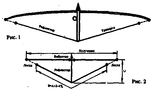
Reflector made of wire, not only reduces the weight, wind resistance and cost of the antenna, but will allow you to apply a lighter boom. In Fig.1 is a General view of this design. With this structure significantly reduces the space required for rotation of the antenna.

Almost all the books for radio Amateurs are chapters on directional antennas. 9 times out of 10 this Chapter begins with a classic V-shaped antennas.
There will be a table that gives the angle between the two shoulders to their different lengths that the gain slightly more than 5 dB for parties, equal to the wavelength, will increase to 15 dB for parties with a length of 10 wavelengths. The gain may be greater if 2 V-return of the antenna to connect, getting a diamond.
Table 1 Frequency (MHz)A - length
vibrator, m C - length
boom, m 14,15010,06 3,50-4,00 21,2006,70 3,00 24,9005,73 2,50 27,2005,24 2,20 28,5005,00 2,00 50,0002,85 1,20
The use of such systems by Amateur radio operators is limited by the space required to install them, plus they are not able to rotate.
I wondered, would the use of the V-shaped element in a YAGI to improve its performance?
And if the improvement will be only 0.5 to 1 dB, then it deserves attention.
DX-men say that in pile-up additional dB can solve everything.
After reviewing the literature, I noted that the primacy in the formulation of this question doesn't belong to me.
In CQ Magazine (August 1983) K4JZB wrote that reached approximately 1 dB increments amplification with elements of "V", and claimed that BIM LWА element is approximately equal to three single-band elements. It's right or wrong?
I continued my search, this time in "ARRAL Antenna Handbook", and must admit I was surprised, after finding in the Chapter on logarithmic single-band Yagi that by increasing the angle V can increase the gain from W to 5 dB! This improvement of the gain was due to the use of the properties of "critical communication," theoretically developed jointly VK2ABQ and G6XN.
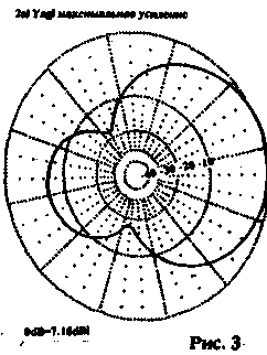
I did a two-element antenna with V-shaped reflector and a conventional direct vibrator (Fig.2) and used it for several years in North Africa. I called it "Jungle Job (approximate value: "exceed my capabilities" - Approx.the translator).
As you may have noticed, looking at Fig.2, "Jungle " Job" is very similar to the bow with arrow (the end of the arrow shows the direction of radiation).


A model was built of bamboo strand. The vibrator was made of wire in the plastic insulation.
The same wire was used in "V the reflector and fastened to the ends of the vibrator fishing fishing line 0.5 mm. Basic dimensions are given in table.1. Take the length, the source for 28 MHz - 5 m and 21 MHz - 6.80 m.
Theoretically, the reflector must be the same length. He will not, as in Yag), more than 3...4%. However, take some stock for final settings (it is always easier to shorten than lengthen).
The lengths may surprise some "experts" on antennas. In fact, the wire in the plastic insulation shall be shortened by 3 to 5% than bare.
It remains to attach the cable of 50 Ohms in the center of the vibrator, and you are ready to work with DX.
Length adjustment of the reflector is necessary if you want to get a better attitude.
Compare Yagi and "Jungle Job"
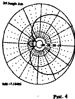
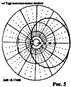
Look at pic.3 gives a radiation Yagi 2-plemennoi of aluminum wires, and compare with Fig.4 (a 2-element beam with a "V"reflector.)
Perfect 2-element beam must have identical currents in the accurate phase in each element so that all the radiation was in the same direction. In other words, the ideal beam should have an infinitely large ratio forward/backward. How to achieve this in practice? In a traditional Yagi to set the correct phase, it is necessary to shift the resonant frequencies of the passive elements (shortening or lengthening).
It's frustrating vibrator, and it needs postoite opposite way (i.e. to extend, when the passive elements are shortened and Vice versa). This, naturally, makes a loss in gain, and setup ends in any compromise between the gain and front/back.
Optimize the antenna either to strengthen or relative forward/backward. Here in the case of improving one parameter worsens the other.
Now consider the "Jungle fob". Here both elements can be tuned into resonance. The correct phasing is achieved by changing the distance between the ends of the vibrator and the reflector. Mathematical calculations show that, theoretically at Dinah frequency the ratio of forward/backward can be up to 30...35 dB. So the antenna occupies an intermediate position between 2-and 3-element Yagi. But in fact it is equivalent to 3 e. Yagi, (compare Fig.4 and Fig.5), which is confirmed by practice.
Author: dick Byrd (G4ZU); Publication: N. Bolshakov, rf.atnn.ru


