This article describes a simplified construction of the multi-channel television reception antenna with a logarithmic periodicity For the manufacture of the antenna needs to have a wooden bar, cable RK-1 and a strip of copper foil. To connect the antenna to the receiver does not require a balun or matching device.
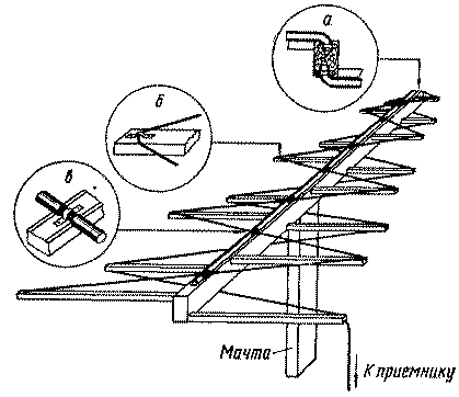
In Fig. 1 shows a General view of the antenna for operation on the I-V channels. Radiating periodic structure is formed by a flexible coaxial cable RK-1, which is connected to the input of the receiver.

The periodic structure of the antenna is mounted on the transverse rails of a wooden beam. The inner conductor of the cable laid in the bottom plane, is soldered to the twisted into a single conductor braided cable, forming a periodic structure upper antenna (Fig, 1,a). The cable is attached to the cross rails using the brackets (Fig. 1,6). Along the top and bottom faces of the beam is necessary to lay a strip of copper foil or copper wires laid in parallel. At the intersection of foil with cable (Fig. 1) must be reliable electrical contact. To do this, remove vinyl chloride cable sheathing, install the bracket and solder the foil to the braided cable. When soldering the cable to the bottom of the structure is necessary to ensure that the melted plastic insulation it, otherwise the cable may be shorted.
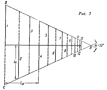
Schematic drawing of a wooden base, to which is attached the cable depicted in Fig. 2. The solid lines show the transverse slats of the upper structure, the dotted bottom.

When building the antenna, using a technique described in the magazine "Radio", No. 8, 1960, p. 42. The base BC of an isosceles triangle ABC is equal to 2l1=lmax/2=3000 mm. structure Parameters it is better to choose as follows: t=to 0.74, a=50°.
The dimensions of the wooden supports for antennas operating on I-XII the channels listed in the table. Channels Ordinal Reiki, n ln, mm Ln, mm I - V 1 1500 - 2 1290 450 3 1110 810 4 954 1170 5 820 1460 6 706 1700 7 607 1910 8 522 2090 I - XII 9 450 2250 10 387 2386 11 333 2503 12 286 2604 13 246 2690
All XII the channel length of the beam must be equal to 2700 mm and cross section of 120X60 mm. need 26 slats, the cross section of which may be 50X30 mm. For five-channel antenna beam length equal to 2100 mm, the number of rails is reduced to 16.
To can be taken from different directions, the antenna is advisable to set on the rotating mast.
The described antenna has a gain of about 6 dB, it agrees well with the receiver.
Author: L. Minas; Publication: N. Bolshakov, rf.atnn.ru


