


")

Designed by the constructor I. Nechaev devices receive the warm response from our readers. Especially liked the simple ham radio design of high frequency devices is a oscillator oscillating frequency in the form consoles to a conventional oscilloscope, the instrument to configure the instrument NTV. Because the hobby of receiving satellite programs is becoming the most popular fans of the television equipment, according to numerous requests from readers of the author developed a simple small indicator for the guidance of parabolic antennas to the satellite, which is convenient to use directly at the installation point antenna.
Compact light designed to provide precise aiming parabolic antenna to a geostationary satellite. He works with the Converter ranges 11 and 12 GHz with an intermediate frequency range 0.85 to 1.9 GHz.... The minimum level of the displayed signal is 50 mV. Powered device, and Converter, or from an independent source voltage 12…20 V or from the receiver reception of the satellite system to reduce cable.
A feature of this design is the selectivity, and unlike similar described in [1], it allows not only to psych up signal, but also to analyze the frequency of the load range of the inverter output signal Converter that enables with great certainty to determine the satellite which held the antenna tuning. This property is very important, as to make initial orientation error of only a few degrees - elementary, the same abundance and close positional location of the satellites may cause you tune is not required, and adjacent to the satellite. Therefore, reliable setup the antenna is normally impossible without visual control taken by programs with the receiver and the TV, and this in turn requires communication between the operator at the antenna and an observer at the TV, which is not always convenient or possible.
Schematic diagram of the device shown in Fig.1. It is built according to the scheme superheterodyne receiver with zero intermediate frequency. In the microwave part includes a current-controlled oscillator of the range 0.85 to 1.9 GHz…assembled on transistors VT3, VT4 [2], buffer amp to VT2 and mixer on VT1. In the tract FC is the HRC transistors VT5 - VT7 and detector diodes VD1, VD2.
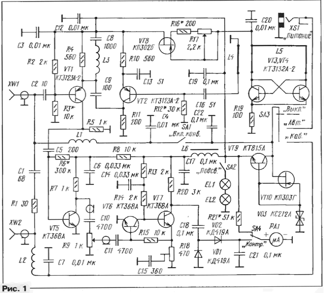
The signal level is indicated by the microammeter RA1. Sensitivity quickly is regulated by the resistor R9.
The transistor VT9, VT10 and the Zener diode VD3 assembled parametric stabilizer the voltage on the transistor VT8 - adjustable current source to power the generator. The oscillator frequency is changed by changing current using resistor R17.
The device operates as follows. The microwave signal from the output of the Converter via nest XW1 is input to the mixer base of transistor VT1, simultaneously the emitter of this transistor receives the signal generator. The if signal is allocated to the resistor R5 and is input to the first stage of the HRC transistor VT5, then the level knob on the potentiometer R9, and with him - on the final stage on transistors VT6, VT7.
The bandwidth of the HRC from about 0.1 to 10 MHz. And since the receiver has zero Central inverter, the total bandwidth is about 20 MHz, which roughly corresponds to the bandwidth of one satellite TV channel. Due to the fact that the satellite signal frequency modulation, energy not focus on a single frequency, as it were, spread out within a certain band frequencies. It enhances the HRC, and then the signal is detected and fed to the level meter - ammeter PA1.
To create normal conditions for work in poor light in the device, enter the backlight is switched by the switch SA2. To control the supply voltage is the switch SA4. It connects the ammeter to the power bus through the resistor R21. The power Converter is performed by the switch SA1, while the operation mode switch SA3: in its upper position the device is switched off, on average, is fed from an Autonomous source (battery batteries or AC adapter) that connects to the socket XS1, and in the lower power is supplied from the receiver through cables. To the nest XW1 connects the Converter, and XW2 cables.
The Converter power supply is made through the filter L1C4, and when powered from the receiver the voltage on the device and the Converter is supplied through the filter L2C7.
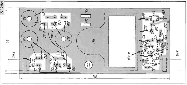
Structurally, the device is made so. It is based on a printed circuit Board from double sided foil fiberglass 1.5 mm thick. at the same time it acts as the front panel, which contains most of the details (in addition to details of the HRC), all the switches, microammeter as well as jacks XW1, XW2 (on metal parts). The sketch Board is shown in Fig.2. Other side to her left metallized and connected by welds along the contour with a shared bus the power of the first party.
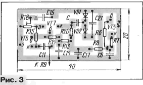
The HRC is assembled on a separate printed circuit Board (Fig.3). It is fixed directly on the microammeter with glue and connected to the common wire in several places.
In your device, you can use the following details: transistors VT1, VT2 - CTA-2, KTB-2, CTV-2; VT3, VT4 - CTA-2, CTB-2, CHA-2, CTB-2; VT6, VT7 - CT, KT315 with alphabetic indices from A to D; VT8 - CPB,IN, KPA; VT9 - KT815, CT with alphabetic indices from A to G and similar; VT10 - CPG, CPD.
In the microwave part of the need to use planar capacitors - K10-17, K10-42 and high frequency resistors C2-10, PH 1-12, the rest you can use km, KLS and similar import. Trimmer - SDR-19, variable - STRs JS4. Fixed resistors - MLT, S2-33.
Coils L1 - L3 are wound wire sew-2 0,4 mandrel of 3 mm and contain 7 9… turns. Coils L4, L5 made in the form of strip lines (see Fig.2) - they similar to those described in detail in [2]. Coil L6 - normalized choke type DM is 0.1, its inductance can be selected in the range of 200 to 500… mcg.
Diodes - any low-power high-frequency, preferably germanium or barrier Schottky, Zener - low-power for voltage stabilization 10…12 V.
Switches and socket XS1 - any small, incandescent - MNT a 6.3-20, microammeter - M4762-M1 with a current total deviation of 200 μa.
When mounting the microwave part of the findings of the details necessary to do the minimum possible length. If you use the body of another configuration, the circuit Board can to redo doing it in any form (except microwave).
The building should start with the settings of the microwave generator. It is better use a frequency meter with an operating frequency up to 2 GHz, it is connected to the collector transistor VT2. In the scheme the position of the resistor R17 selection resistor R16 install the lower edge frequency of adjustment, and choice of resistor value R17 choose the range of adjustment. In the author's copy of the device frequency the generator was changed from 700 MHz to 2 GHz when the current through the transistors VT3, VT4 from 13 to 0.8 mA. For more smooth setting will have select resistor R17 with a small leap of initial resistance and logarithmic characteristic.
If you don't have the frequency for configuration, you can use your receiver. For this its input is connected to the input of the device (socket XW1). The receiver on rebuild frequency, and a resistor R17 to the same frequency, set the generator point settings determined by the appearance of a signal in the form of interference on the TV screen. Thus it is possible to calibrate and scale of this resistor.
Then the resistor R9 is set in upper circuit position and resistor R18 installing such a noise that the arrow pointer device slightly deviated. After that, it is advisable to check the sensitivity and range adjustment by measuring the microwave generator. If you do it is impossible, it is necessary to connect the device to the Converter, set on a customized antenna. The noise should increase, and after that, rebuilding the device according to the frequency, tune to satellite channels.
If the shooter rolls, the resistor R9, the gain should be reduced. Tuned on weak signals far removed from the more powerful, the selection of the resistor R3 achieve maximum sensitivity. For ease of reference on the scale make a mark most often taken by satellite of television programmes, for example, "NTV-plus" or "Eurosport", for different polarizations. Occasionally connect to the Converter arrow constantly rolls in any position of R9 or rolls over in certain parts of the range - this means that, rather just device snowspeeders. You have to carefully perform the installation, to reduce the length of the connecting wires and possibly increase the capacity bypass capacitors.
In the presence of the measuring scale generator of the device can establish this in units of voltage, in this case, the resistor R9 is necessary to replace the switch with resistive divider, which will perform the functions of a fixed the attenuator.
Literature
Author: I. Nechaev, Kursk