When receiving a TV program, ham radio operators are often faced with difficult conditions, when the signals come from different directions, with different polarization, etc. the Author published article below has solved this problem quite simple means, using goal sets a half-wave vibrators and optimizing all sizes for minimum SWR in the famous readers log the program MMANA.
The advent of affordable computer programs for the calculation of antennas allowed a new take a look at their development and to combine the experiment with software optimization. And, as it turned out, improvement and optimization lends itself to even the most the simplest-minded television antennas half-wave vibrator, with which, at first glance, doing seemingly nothing. We are talking about adding to him one or more vibrators. Below options have been considered improvements. Their development, manufacture and adjustment was accompanied optimization of parameters known to the readers of the magazine the program MMANA. Basic the task was this: to achieve the expansion of the bandwidth of a half-wave vibrator with the ease of fabrication and low material costs.
Family designed antenna includes a dual-channel design on various channels and band spanning multiple channels. The antennas consist of tuned vibrators within a certain distance from each other. Only one of them (with a gap between the halves) is active, i.e. it connected to the feeder.
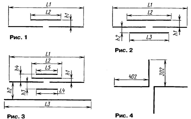
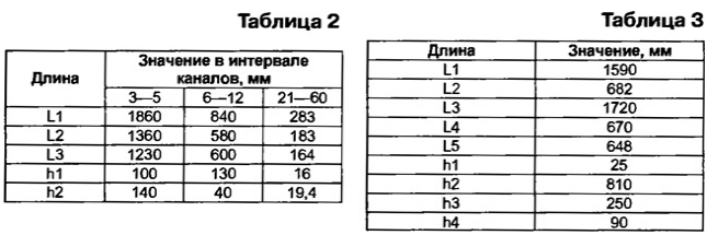
A schematic representation of a two-channel antenna is presented in Fig. 1. Range channel meter waves (MB) is divided into low cut (channels 1-5) and HF (channels 6-12) the sub-bands. Channel bass vibrator is determined by the L1 and the HF vibrator L2. The distance between the active half of the vibrator about the Size of 40 mm. vibrators for MB various channels are listed in table. 1.

Vibrators are made of pipes with a diameter of 15 mm copper or aluminum alloys. You can also use rods or strips of the same material. Input the impedance of the antenna is determined by the length of the vibrators, the distance between them and their diameter. Thus, to obtain the input impedance, 75 Ohm, when the scale of the distance between the vibrators should be 53 mm.
For approximate conversion of the antenna parameters on the other input resistance or by changing the diameter of vibrators available formula

where h is the distance between the vibrators; To - antenna impedance or the diameter of the vibrators in the same units of measurement. The formula is valid for tube diameters from 7 to 20 mm and the input impedance from 25 to 300 Ohms.
For example, if the diameter of the vibrator is 10 mm, the distance between them

If you need an input impedance of 100 Ohms, the distance between the vibrators

Sizes can be specified by optimizing for minimum SWR in the program MMANA.
It should be noted that for antennas with dipole woofers, tuned to the second channel, the radiation pattern will be distorted: it becomes three fold. It due to the fact that some frequency RF sub-band is close to a multiple of the frequency this channel. However, the second channel is mainly used in weekends converters UHF-MB collective antennas. So the loss is small.
By the way, this antenna is easy to conduct experiments in a wide range frequency by fabricating a removable or telescoping half-wave vibrators. The active vibrator should be minimum two times longer passive.
Balancing antennas we can use the so-called TDL - transformer on long lines. To craft it you will need a ring ferrite, preferably high frequency, with external diameter more than 10 mm. Line do of two copper wire sew-2 or PETV. Fold them in parallel, and they wear tight soft insulating tube. The diameter of the wires is chosen the maximum possible, but not more than 1.7 mm, so that the ring fits four or five turns of line. Transformer include the half-vibrator (to him connect the start wire line and coaxial cable with wave 75 Ohm (it is connected to the ends of the wires of the line). Can use also balun device from the previously room antennas.
A similar structure may have antenna decimeter waves (UHF). However, as shown by calculations and experiments on UHF is better to use a band antenna, covering almost all the channels from 21 to 60.
Band antenna differs from dvuhkanalnyy that consists of three vibrators. Its construction is shown in Fig. 2, and dimensions are possible in table. 2.
The diameter of the pipes for channels 6-12 MB may be in the range of 10 to 15 mm. For diameter 15 mm, in the frequency range from 172 to 228 MHz VSWR does not exceed 1.3, and for of 10 mm diameter in the range of 170.. .230 MHz - no more than 1,55.
For the antenna on channels 3-5 (75... 100 MHz) MB with a diameter of 20 mm pipes SWR - not more than 1.5. With decreasing diameter of 10 mm, the CWS may increase to 2.

On UHF when the diameter of the pipes of the active vibrator 7 mm and the other 4 mm vibrators SWR antenna for channels 21-57 does not exceed 2. On the higher frequency channels 57-60 The CWS rather abruptly increases.
Adding a few more items, you can greatly improve aiming the properties of the considered antennas. As an example, in Fig. 3 shows the antenna on channels 4 and 10. The sizes are listed in table. 3. Pipe diameter - 10 mm. Coefficient antenna gain is equal to 5.7 dB, the ratio of front/rear and 9.8 dB at the Central the frequency of channel 4. The same for channel 10 to 6.9 and 12.8 dB, respectively.

On other channels the antenna of this design can be calculated by the program MMANA in the following order.
1. The minimum SWR is determined by the size of bass vibrator (active).
2. Do the same in size HF vibrator and distance to active.
3. At a distance of about 0.1 wavelength for active bass vibrator feature reflector length, somewhat greater length of the active vibrator, and optimize the size of the reflector and the distance from the LF oscillator for minimum SWR and maximum the ratio of front/rear.
4. At a distance of about 0.1 of the wavelength of the RF Director place before HF vibrator and the reflector RF for active vibrator. Their original length is taken as the length of the vibrator HF.
5. Optimize the size of the Director, the vibrator and the reflector RF and the distance between them the minimum SWR and maximum ratio front/rear.
Consider one of the options multichannel reception antennas, the elements of which performed as described above.
As the mast used plastic pipe with a diameter of 40 mm. Antenna consists of three tiers. This is due to the fact that in Donetsk the possible reception of signals multiple channels from three directions: one - sixth of the channel, in another - fourth, tenth and UHF channels, in the third to twelfth channel vertical polarization.
Active vibrators sixth and twelfth channels for different polarization United in one structure, forming the first (lower) tier. Their location in the vertical plane and the dimensions shown in Fig. 4. The distance between the horizontal halves of the vibrator 20 mm. Vertical dipole placed inside the mast.
The antenna parameters on the sixth channel can be improved by adding a Director with a length of 700 mm and reflector length 850 mm away from the active vibrator respectively 270 and 900 mm. design parameters at a frequency of 178 MHz: SWR is 1.3; the ratio gain - 7 dB; the ratio of front/rear - 15 dB. At a frequency of 226 MHz VSWR equal 1,1.
The second tier is a two-channel antenna that is tuned for the fourth and tenth channels. From the top of the mast (the third tier) is a broadband antenna UHF amplifier, which is located inside the mast. Used amplifier SWA-9, which input transformer switch to the matching device. For this average input output (two wires) of the transformer is disconnected from the common wire. Monochrome input conclusions (now four) connect transformer interconnected and connected to the halves of the vibrator antenna.
Considered antenna works for about three years, ensuring the normal the image on ten channels (four on MB and the other on UHF). Development, of course, does not claim exclusive novelty, however, this antenna was enough for a reception in difficult conditions.
The simulation program MMANA antenna
The files of the antennas described in and calculated in this the program
Author: G. Alekhin, Donetsk, Ukraine


