


")

Difficulties with the orientation of the antennas are facing many hams. To facilitate this process can special devices - tunable indicators or level meters. In particular, in "Radio" № 11, 1996 (pp. 8, 9) was the described device for orientation of the antennas in the range MB. In the published article here reviewed a similar device for the UHF range.
Development of a network of terrestrial television broadcasting in our country is on the path input the new transmitters operating mainly in the UHF range. Very it is often difficult to achieve high-quality reception of TV signals in this range. Most new transmitters usually have small capacity, low installation height of the transmitting antennas, often located in different urban areas.
All this leads to the fact that the use of indoor antennas becomes impossible. You have to effectively use directional antennas, place them outside dwelling premises and at a considerable distance from the TV. In turn, this causes the additional attenuation of the signal in connection cable, forcing apply antenna amplifiers. In addition, there is the problem of orientation antennas.
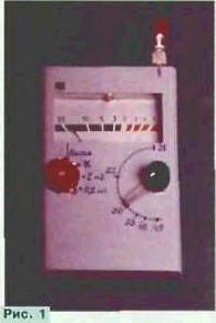
In solving these problems will help for review radio Amateurs a relatively simple device. It allows to significantly simplify the procedure the orientation and approximate way to determine the level of the received television signal. Its dimensions are small (see Fig. 1, much like a pack of cigarettes), so it is convenient to use when the orientation of the antennas in various locations.
The device was developed at the request of readers on the basis of similar circuitry device for the range of MB, is described in "Radio" earlier. Its easier (see Fig. 2), and dimensions - less. The device is a receiver direct signal conversion UHF range and contains an RF amplifier (VT1, VT2), heterodyne (VT3), mixer (VT4), amplifier (VT5, VT6) and amplitude detector (VD1, VD2). The received signal is indicated measuring head RA1.
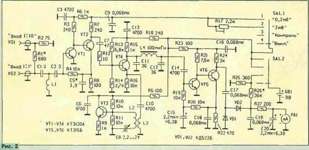
The television signal is supplied to the RF amplifier is assembled on a two-stage the scheme with deep negative feedback DC via the resistor R4. At the input of the RF amplifier is set the high pass filter C1L1C2 that suppresses signals below the UHF range. For the extension of the interval indication of the level of received signals at the input has two RF connectors. Through connector XS1 radio signal from the antenna is fed to the high pass filter. Submitting the same signal connector XS2, you can loosen it tenfold. The transmission coefficient of the RF amplifier equal to about 15 dB, and frequency response in the frequency range 470…not 800 MHz exceeds 1 dB.
The amplified signal reaches the mixer. There the signal is lo. The resulting signal through a low pass filter С11L4C12 with a cutoff frequency of 4 MHz passes to the amplifier.
The local oscillator is built on a capacitive treatacne. Its frequency rebuild the variable capacitor C8. With mixer, the local oscillator is connected through coupling coil L3. He works in the interval DM V. Band converted frequency equal to 0.02 AR4 MHz. Since in the illustrated embodiment of the mirror device the channel is not suppressed, then the total bandwidth is approximately 8 MHz, which corresponds to the width of one TV channel.
The selected video signal passing through the amplifier, the amplitude is detected detector, and the resulting voltage is measured by a dial indicator.
The device operation mode change switch SA1. In his position 4 is "Off." the power supply for the device is not received. In position 3 - "Control" to the battery power connected resistor R25, through which flows a current equal to consumed by the device. Through the resistor R26, the battery voltage comes on dial indicator PA1, which control its value.
In positions 1 and 2 switch the device operates in the indicator mode. In position 1 - "0.2 mV" the battery voltage is supplied directly to all nodes of the device and the maximum value of the dial gauge readings is 0.2 mV. In position 2 - "2 mV" supply voltage to the RF amplifier comes through trimmer resistor R17, the gain of the RF amplifier is reduced, and the maximum value of the scale will correspond to 2 mV. In addition, the sensitivity can be reduced by a further ten times, giving a signal at the connector XS2. Consequently, the indicated maximum level is 20 mV, and the minimum is determined by the sensitivity of the whole device and is in the range of 20 to 40 mV.
Structurally, the unit is placed in a plastic housing dimensions 100x65x25 mm. In this part it serves as battery compartment, and for other parts remains an area the size 60x65 mm. Here fixed dial the M4761 having large dimensions and relatively small scale electromagnetic system. For the indicator on the front panel is made rectangular window the size of 50x25 mm dial indicator Itself is modified: removed parts of his body with two sides near an electromagnetic system. If to use the indicator of smaller dimensions, for example M4762-M1, this revision it is not required.
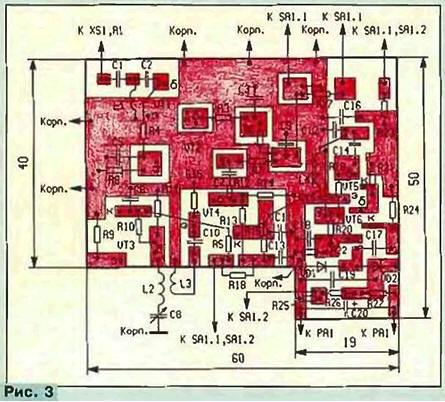
Most parts are on the PCB of bilateral foil fiberglass, a sketch of which is shown in Fig. 3. The party free from parts left metallized, she plays the role of screen connected in several places around the perimeter with the common wire of the other side Board.
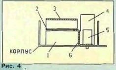
Placement of units of the device within the housing shown in Fig. 4. Dial indicator 1 glued to the bottom of the housing, which serves as the front panel. The indicator paste the printed circuit Board 2. Near electromagnetic system 4 indicator one side is mounted on the housing of the variable capacitor 5, and with another switch (obstructed system 4). Under the condenser in front of it installation you need to put a strip of foil b of tinned copper, which should to be connected to the common wire and the screen of the PCB 2. To resolve the influence of hands on configuration of the device part of the Board, on which is placed high-frequency elements, it is necessary to close the screen 3 foil or thin one-sided foil fiberglass, combining it in foil several places with the common wire.
The device can be applied, except indicated in the diagram, the transistors CT(VT1-VT4) with any letter index, CTV, CTG, CTA - CTG(\A,UT) or similar. Diodes - KD521, CD. CD with any letter index. Capacitors C15, C20 - C50, K53. The variable capacitor C8 - KVM with air dielectric. The remaining capacitors - km, KD, KLS. Permanent resistors - MLT C2-33 or C2-10, rigged R17 - SDR-19. During installation resistors and capacitors in the high frequency device units their findings should shorten to the minimum possible length.
Coil L1 wound wire sew-2 0,2 mandrel with a diameter of 2 mm and contains three coil with lead lengths 2…3 mm. Coils L2 and L3 are wound on the same mandrel and contain respectively three and one coil of wire sew-2 0.8. Coil 12 installed between the respective circuit pad of the PCB and the output the variable capacitor C8, and the coil L3 is placed close to 12. Coil L4 Is the throttle DM is 0.1.
Establishing device to start with verify that the local oscillator and install its limits of adjustment. If it is possible to use a frequency meter, it is connected to the coil L3. Otherwise, you have to use TV, which is tuned to the low frequency 21 channel UHF and bring the antenna close to the local oscillator. The rotor of the capacitor C8 set to the maximum capacity and bringing together or moving apart the turns of the coil 12, achieve the appearance of the lo signal in this channel.
Further, the rotor of the capacitor C8 is rotated to the position of minimum capacitance and check on what frequency the heterodyne channel operates. Sometimes it's necessary to do approximately, as most modern TVs do not have an exact pointers number or the channel frequency UHF, Have to rely on signals working transmitters.
For these in the scheme of values of the variable capacitor heterodyne rebuilt from 470 to 650…670 MHz, i.e. from the 21st to the 44th channel. If that is not enough, you need to use a variable capacitor with a large one and a half times the value of the maximum capacity, and the coils L2, L3 wound on a mandrel of smaller diameter.
If it is possible to configure the RF amplifier, using a measuring device, do this, first disable the on time of the supply voltage from the local oscillator. The selection of capacitor C5 provide lower frequency response in a desired frequency interval.
Then, turn the power of the local oscillator to the input of the instrument served with exemplary generator signal amplitude 1 …2 mV and a frequency corresponding to the middle interval adjustment. The device is in switch position 1, adjust capacitor C8 by the maximum indicator. If his arrow surpasses, the level of the signal generator is reduced.
Further, by changing the signal level of the generator, determine the levels: the first is when the device is clearly its registers, i.e. when the arrow deviates markedly, and the second - when the indicator needle is at the maximum point of the scale. First the level corresponds to the sensitivity of the device. If the second level is within 0.1…0.5 mV, it is possible to calibrate the scale indicator. If it is more - increase the gain in the if amplifier using transistors a high gain.
Set the switch to position 2, and a signal generator with vcesat times greater than the maximum signal in the switch position 1. Trimmer resistor R17 achieve deflection of the indicator at the maximum mark scale. Reduce the level of the signal generator and graduate scale of the device in the mV or decibels. Finally, graduate scale of the variable capacitor capacity. This is best done in the UHF channel numbers.
If you don't need the graduations of the scale indicator or is unavailable, do not, leaving it non-graded. In this case, the device performs functions relative indicator that the orientation of the antennas is quite acceptable.
In conclusion, from the regulated power supply set voltage corresponding to nominal for battery, and choose a resistor R26 arrow deviated to the marked point of the scale, for example, maximum or average. After this reduces the voltage to a level where the parameters of the device will be deteriorated, for example, "go" frequency or decrease the sensitivity, and celebrate it the deviation of the arrow on the right of the indicator. When the battery voltage should not to fall below such value.
The device is powered by a battery voltage of 9 V. the Maximum current consumption is 22…25 mA.
It should be noted that the RF amplifier can be used separately to build antenna amplifier UHF range. Using one such amplifier, get the gain is about 15 dB, and two, connected in series, - 28…30 dB.
Author: I. Nechaev, Kursk