Yet again ultramarathoning ask my senior colleagues: "What antenna should I choose?" To accurately answer this question, as it all depends on for what purpose built antenna. If there are ties in all directions, for example inside the city. very convenient antenna with a pie chart, which often allow you to work at distances between stations equal to 50-100 km For long-haul communication more suitable directional antennas. In greatest abundance ultramarathoning areas or in cases where some areas still static, it is obviously better to use narrow-beam antenna.
These few examples are enough to understand that the antenna is equally fit for all occasions, no. Amateur radio operator himself must choose the antenna that meets his requirements. And even better to build two or three antennas and use them as needed.
Novice ultramarathoner unwise to choose its first antenna any bulky and complex structure, in the process of construction which he is inexperienced can make a lot of mistakes. Should start with building simple antennas and with the growth of experience and knowledge to move on to more complex systems.
When choosing the type of antenna you need to consider what the basic materials available to the designer. If you cannot purchase pipes or rods for antenna elements, it is possible to choose, for example, a "double square", in the construction of which requires only a wire, wooden slats and a small amount of insulating material. Substantially also, as long as the Supply line from the coaxial or ribbon cable, or simply in the form of a two-wire line.
You cannot lose sight of the fact whether during the construction of the antenna any measure. For a beginner, besides not possess a measuring instrument, it is better to choose the antenna that will be work well without tuning.
Discuss several types of antennas. Among them are simple designs that is available to repeat each newbie and sophisticated, including antenna systems, which may be of interest to more experienced "hunters" for DX. Since most of our ultramarathoning operates in the 144 MHz band, the dimensions of the antennas are Given for this range.
The reader will notice that for none of the antennas are not technical details of the design. But this should not prevent the construction, as the methods of operation and many of the details described in any radio Amateur's Handbook.
THE CIRCULAR ANTENNA RADIATION
Cruciform dipole. The antenna consists of two half-wave vibrators 1 at an angle of 90° to each other (Fig. 1). Chart radiation of this antenna is not a perfect circle, but practically it gives quite a nice circular radiation. Since the impedance of a single dipole is approximately 70 Ohms, in parallel operation of two dipoles impedance is about 35 Ohms. Such coaxial cable at our disposal is not, so it is best to feed the antenna through a quarter-wave transformer 3, made of 50 Ohm cable. From the transformer to the equipment is 75 Ohm cable 4. From the same cable balun made U-2 knee.
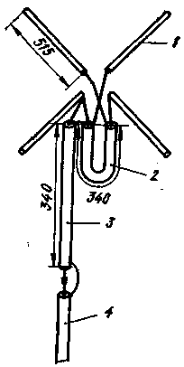
Fig. 1
Vertical antenna (Ground Plane). The emitter 1 (Fig. 2) and radial .the conductors 2 provide a pie chart in a horizontal plane. The angle between radial conductors and the emitter determines the impedance of the antenna.
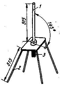
Fig. 2
At an angle of 90° impedance is about 30 Ohms at an angle of 180°- 70 Ohms. Usually choose the angle of 145°, which allows to feed the antenna with 50-Ohm-NYM cable. Cable connected to the connector 3 mounted on the metal plate, which is electrically connected radial conductors. An emitter which is connected to the center conductor of the cable, is mounted on the insulator 4.
DIRECTIONAL ANTENNAS
"Double square". This popular guided LW antenna used and on УSW (Fig. 3,a). The coefficient of gain (compared to half-wave dipole) reaches of 5.7 dB, the ratio of the radiation forward/backward - 25 dB.
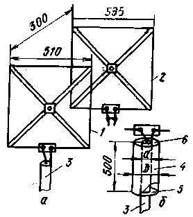
Fig. 3
The distance between the vibrator 1 and the reflector 2 is chosen equal to 0.15 lambda that allows you to power the antenna 75-Ohm coaxial cable 3. Experience has shown that thus fed antenna works quite satisfactorily. Adjust the antenna using a short-circuited loop, included in the gap of the frame of the reflector.
Balancing the antenna can be used Cup quarter-wave (Fig. 3, b), connecting it to the active ends of the vibrator 1. The Cup consists of a metal cylinder 4 with two covers - metal 5 and the dielectric 6. Inside the Cup is a cable 3, the cable sheath is connected to the cover 5. The diameter of the Cup should be 3-4 times larger than the diameter of the cable.
For the manufacture of antenna elements, you can use copper or aluminum tube, tape, or wire of various diameters. "Double square" takes up very little space, structurally simple. This antenna has a relatively good characteristics. It is worth considering the possibility of placing antennas of different ranges on the same cross rails.
Triangular antenna (Delta Loop) belongs to the same family as "square" as the active perimeter of the vibrator is approximately equal to the wavelength. The feature of this antenna is that all the elements of its design are metal. The author of antennas advised to feed it with 50 Ohm coaxial cable, but for this purpose and successfully use 75 Ohm cable. The simplest triangular antenna shown in Fig. 4. Active vibrator 1 configured using gamma matching device connected to the cable 3. Depending on the availability of measuring devices are setting the minimum SWR or the maximum signal strength. The reflector 2 is often easier to make unregulated.
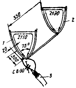
Fig. 4
With a triangular antenna experimented UA1WW. He advises to apply the 5-and 9-cell options. Last, due to the narrow horizontal angle of radiation, especially suitable for holding long bonds. Figure 5-element antenna is shown in Fig. 5. Here 1 - active vibrator, 2 - reflector, 3 to 5 Directors. Since this is completely new for our ultramarathoning antenna, here is some constructive information.
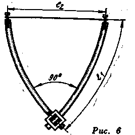
Fig. 5
For carrier beam is more suitable 4-sided dural tube with a side of 18-20 mm square, it is much easier to mount the elements than in a circular pipe (see Fig. 6).
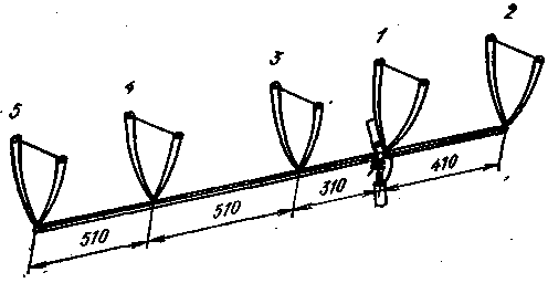
Fig. 6
The antenna elements are made of copper or aluminum tube or rod with a diameter of 6 mm, the horizontal side of the wire diameter of 3 mm. the Size of elements (in accordance with Fig. 6) are these:
length l1 mm
length l2 mm
Reflector
750
720
Active vibrator
710
680
The first Director
660
670
Second Director
660
650
The third Director
660
630
Triangular antenna - object of interest of ultramarathoning around the world. Taking into account the positive experience of working with her, we can assume that she will soon become one of the most popular antennas. So please note those wishing to experiment on one particular of its type - double triangular antenna (Fig. 7). The sizes of the triangles of this antenna is slightly better than the single; the perimeter of the reflector is equal to 2266, active vibrator - 2116 and Director - 1993 mm. the distance between the reflector and dipole-0.2 lambda, between the vibrator and the Director-0,15 lambda.
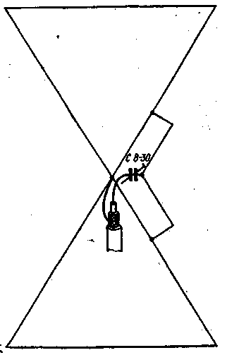
Fig. 7
According to some data were obtained such gain dual antenna (compared to half-wave dipole):one element (the active vibrator) - 3-4 dB: two elements (the vibrator and the reflector) is 8-9 dB: three elements (reflector, vibrator in Director) - 10-11 dB. It seems that this is a perspective view of the antenna and they need to do.
10-elementa antenna (Yagi). Undoubtedly, this is the most popular УSW antenna (Fig. 8). It gives the gain of 13 dB. The author conducted using such antenna meteoric links with England and Belgium, a lot of long ties at the expense of tropospheric passing and "Aurora".

Fig. 8
The passive antenna elements are made of a bimetallic wire with a diameter of 4 mm, and the folded dipole active - 15-Milli-meter copper tube and wires. Characteristic impedance at the feed point is equal to 300 Ohms, so a 75-Ohm cable is connected through U-knee with a length of 68 cm.
The length of the carrier beam is somewhat greater than 3.5 m, diameter - 20 mm. the length of the reflector 7-1060, vibrator 2-990, Directors 3 - 10 - accordingly 933, 930, 927, 924, 921, 918, 915 and 912 mm.
The antenna on multiple bands. There are circumstances when to install more than one antenna fails. But in addition to antennas for radio and television often need! Then the solution is very simple - УLW antenna on several bands. One of the variants of this antenna is shown in Fig. 9, a (top view) and 9 b (axonometric projection). It can be successfully used in the range from 50 to 220 MHz. The antenna gain at the frequency of 50 MHz 7 dB 144 MHz 12 dB, and 220 MHz - even of 13.5 dB. This antenna has two floors. At the frequency of 50 MHz on each floor are on two angled vibrator 1, located at a distance of lambda/4. At a frequency of 144 MHz length equal to about 3/4 lambda and therefore have V-shaped antenna. At a frequency of 220 MHz vibrators have a length of 5/4 lambda.
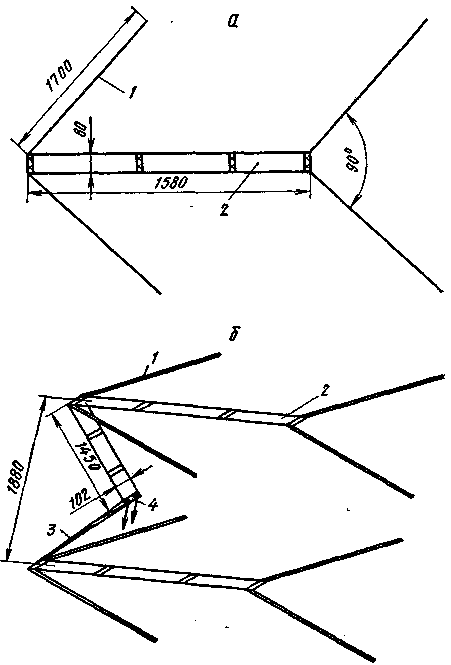
Fig. 9
The vibrators are connected by a two wire line 2, and both floors - 3 lines, the length of which depending on the range is from 1/4 to 5/4 lambda. The distance between floors, if desired, can be modified to the extent permitted by the length of the 3 lines. The input impedance of the antenna at the feed point 4 at frequencies of 50 and 144 MHz to about 300 Ohms at a frequency of 220 MHz it drops to about 200 Ohms.
The antenna elements can be made of a tube or rod: the vibrators - diameter 10 mm; lines 2 - 12 mm (10 mm, then the distance between the centers of the wires of the line should choose equal to 64 mm) lines 3 - 6 mm diameter).
Author: K. Kullamaa (UR2BU), Tartu; Publication: N. Bolshakov, rf.atnn.ru


