Recently interest has grown in the framework antennas. If you had such antennas were used relatively rarely, but now they are used as antennas for mobile communication systems, intruder alarm systems, etc.
The main advantage of such antennas is significantly less influence of environment on the parameters of the loop antenna, which in some cases is decisive in choosing an antenna. However, use of such antennas with dimensions commensurate with the wavelength L, in the range of LW is very difficult. It is therefore of particular interest to use the loop antenna with a perimeter of S, the smaller the wavelength L. this antenna can be used as additional, dealing with their one-sided orientation, and install them in Windows, loggias, balconies, as well as in complex directional antennas in the low-frequency SW bands. The basic element of such antennas is a frame with a perimeter of S, the smaller the wavelength. For placement on the Windows, balconies most suitable form of frame is rectangular. Consider this frame with the perimeter of S, is equal to the wavelength L, located in the vertical plane[I].
When feeding this antenna with vertical side elements of both of these elements are excited in-phase, and they are current antinodes and nodes of the voltage. Horizontal elements with loops of voltage, in turn, energized the anti-phase. The vertical elements can be represented in the form of two parallel vibrator with a curved tip placed at a distance of L/4 and excited in the same phase. Due to the addition of fields of these dipoles excited in phase, the maximum field strength in the horizontal plane is in the axis direction of the frame perpendicular to the plane of the loop antenna.
Such a distribution of currents and voltages along the frame considered for the case S=L, is kept at a somewhat reduced S compared to L. In further reducing the size of the loop antenna changes the current distribution on the perimeter of the frame, and with significantly reduced dimensions compared with L (S/L<0,25) instead of nodes and loops of current, a uniform distribution of the current (current is almost unchanged along the frame). The current in this case, at each moment of time flowing in one direction, therefore, common-mode, and therefore any radiation oppositely located portions of the frame folds in space in opposite phase, leading, unlike a full-sized frame, to the minimum tension in the direction of the axis of the frame. Thus, such a frame by its radiating properties is similar to a conventional inductor, to make which can radiate only greatly increasing its quality factor Q and increasing the current.
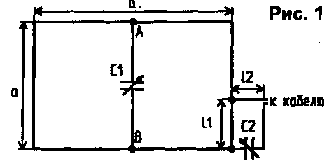
However, the efficiency of such a radiating antenna will be very small because of the low radiation resistance of R-OBS, and therefore, the small antenna radiated power of the radio isotopic laboratory [2]. Therefore, a more appropriate is the use of antennas with a velocity factor of 0.25<K<1 (K=S/L), which, despite the reduction in efficiency compared to a full-sized frame, good radiate and have a maximum radiation in the direction of the axis of the frame. One way to reduce the resonant frequency of the loop antenna is the inclusion of the capacity in point of the antenna .with a maximum out-of-phase voltage [W]. In this case it is possible a significant reduction in resonant frequency. At the same time, a similar reduction of the frame frequency to be used at lower frequencies, leads to a reduction relation S to L, and consequently to a significant reduction in the radiation resistance of the radio isotopic laboratory, as defined in [4] the ratio of CISL=197(S/L)4. In this case, the immediate inclusion of cable in the frame for its power, as is often done when using a full-sized frames, it is impossible. To coordinate the frame with a cable with a low of CISL used - or O-coordination [1,3]. Diagram of a loop antenna with shortening capacity and alignment is shown in Fig.1.

In the considered embodiment, the vertical excitation elements point to the midpoints of the horizontal elements A and b have minimal out-of-phase voltage. This also means that the resistance between these points is quite large (on the order of shortfall).
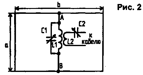
Antenna power can be realized by the inclusion of these points in the resonant circuit, also having a large resistance at the resonant frequency. In this case, the agreement between the antenna feeder is the selection of the transformation ratio when connecting a cable to a part of the coils of the resonant circuit. In addition to auto transformer, potential transformer connection of the cable and the circuit through the coil connection. Along with the possibility of excitation and approval, the inclusion of the contour at point A and also reduces the self-resonant frequency of the loop antenna due to capacity, which is part of a parallel resonant circuit. In this case, the capacitance value of the resonant circuit in the tuned antenna is somewhat larger than in the case of a single circuit that is configured to the same frequency. Diagram of the antenna with a resonant circuit is shown in Fig.2.

To check the efficiency of matching and shortening of the antenna using a resonant circuit made of two rectangular loop antenna with perimeter S=5.6 m and S=12.8 m. Both antennas were made from copper wire of diameter 2 mm and mounted in the window opening on the balcony and a nine-storey building. The antenna was tuned and verified with the cable with impedance of 50 Ohms in two ways: shortening capacitor C in alignment and with the help of the resonant circuit. The calculated resonant frequency of this framework - 53 and 23 MHz, and experimental - 38 and 21.2 MHz, respectively. The offset of the resonance frequency in comparison with the design value due to a significant capacitance between the frame elements and metallic elements: valves, plums, balcony railing, etc.
Experimental determination of the resonant frequency of the framework was carried out by the generator G4-18 and an indicator field (for operation at frequencies above 35 MHz in parallel with the generator output 0,1... 1 is included In the diode and the antenna tuning is done using the 2nd harmonic of the signal frequency). Resonant circuit of the 1st antenna consists of a coil of inductance 35 mm in diameter with 5 turns of wire with d=2 mm (the length of the winding -20 mm), and a variable capacitor 12...495 PF. The transformer connection is implemented by a coil consisting of 1 round, and at a frequency of 14 MHz - 2 coils arranged on the surface of the coil of the resonant circuit. Compensation of the inductance of the coil connection is performed by the capacitance C2. Resonant circuit included in the second antenna, comprised of an inductance coil with a diameter of 35 mm, containing 29 turns of wire d=l mm (the length of the winding - 65 mm) and a capacitor. The coil had 3 coils of wire d=l mm, the Resonant frequency of antennas, the dimensions and parameters of the matching elements in the table.
With shortening capacity (Fig.1)
With a resonant circuit (Fig.2)
The tuning frequency G, MHz
Yorac. the capacitance C1 (pF)
The loop length 11,
CM
These compensate. the capacitance C2 (pF)
CWS
>The circuit capacitance C1 (PF)
The capacity of the communication circuit C2, PF
CWS
a=1.4 m; b=1.4 m; S=5.6 m; fтеор=53 MHz; fрез=38 MHz
29
b
31
20
1,05
38
22
1,06
21,2
12
38
50
1,3
80
48
1.3
14,2
30
45
85
1,5
116
100
1,5
a=5 m, b=l,4 m; S=12,8 m; fтеор=23 MHz; fрез=21,,2 MHz
21,2*
1.1
14,2
12
48
50
1,2
25
50
1,2
7,05
50
70
80
1,4
100
100
1,5
* -At a frequency of 21.2 MHz frame ate cable, directly included in the middle of the vertical element.
Found that when using both systems setup and alignment is achieved relatively low SWR (approximately the same for different methods of coordination), but the process of agreeing and setting varies greatly. When using shortening capacity and-matching this process looks quite complicated and consists of several stages: setting the frame to the desired resonant frequency, and then the successive change of the loop length, the distance at which it is located, and a capacitance, inductance loop, followed by setting the resonant frequency and the control of the CWS. This process of harmonization and tuning causes considerable difficulties, especially in the absence of sufficient experience.
Matching with the resonant circuit is much simpler: the antenna is adjusted by changing the capacitance of the resonant circuit, and then changing the transformation ratio of the minimum SWR (sometimes requires the inclusion of the capacitor C2 compensates the inductance L2.) It should be noted that despite the fact that nizkochastotnykh ranges achievable significantly lower VSWR, efficiency of the antenna as a radiating system is primarily determined by the efficiency.
If most of the full-sized antennas this parameter defines
R OBS Rизл
n=--------- - -----------------
Cod Rизл+Rпотерь
close to 1, then a shortened antenna with the impedance of the radiation Rизл comparable to Rпот, efficiency is significantly reduced. Therefore you should always remember that a very short antenna is radiation transform input energy into heat. Regardless of the method of matching and setting, shortened antennas are narrowband and require no adjustment when changing frequency. And if for the antenna with the alignment and shortening capacity, the restructuring process must be repeated almost all these steps when you change the frequency, then the antenna with a resonant circuit the process of adjustment is reduced to a small change in the capacitance of the resonant circuit. It makes such antennas is very convenient, especially when item availability settings.
Literature
1. Rothammel K. Antenna. - Moscow: Energiya, 1969
2. Grechikhin A. Electrically small antennas: opportunities and misconceptions/ /Radio. - 1992. - No. 11. - P. 8 -10.
3. Key to 3., Lipinski, E. Amateur antenna short and ultrashort waves. - M.: Radio and communication, 1983.
4. Meinke X., Gundlach F. Radio guide. Vol. 1. M-L, SEI, 1960.
Authors: M. Anisimov (UA3POC), M. Anisimov (UA3PML), (Tula); Publication: N. Bolshakov, rf.atnn.ru


