1. Definition and concepts
Unbalanced (pin) is called the antenna placed directly at the earth (or metal screen) perpendicular (less inclined) to its surface.
If we assume a perfectly conducting earth and consider mirroring, the unbalanced vibrator can be considered as the half of the equivalent dipole (Fig. 1).
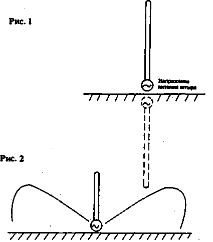
The radiation resistance single-ended vibrator is two times less than that of the equivalent dipole, because the same currents first emits twice as less power (no radiation into the lower half-space) [1].
Input impedance unbalanced vibrator is two times less than that of the equivalent dipole, because when odinakovuh currents of the first power supply voltage is two times less (Fig. 1).
The coefficient of directional single-ended vibrator is two times more than the equivalent dipole, because odinakovoi radiation power first provides up to twice the angular power density, because all his power is radiated in one half-space (Fig. 2).
The same is true for an ideal single-ended vibrator that is when the earth is a perfect conductor. However, if the land has poor electrical properties, radiation field of the vibrator is changed. In addition, this leads to a decrease of the amplitude of the current in the vibrator and, consequently, to the increase of its resistance and reduction of the radiated power. The soil is an insulator with a large dielectric constant (almost $ 80), which alters the electrical length of the imaginary dipole, and the path length of displacement currents. The result - a complete distortion of the directivity diagram (lifting the petals up and disappearance of the radiation at small angles to the horizon) and increase the resistance of the pin.
For this reason, practically do not use the soil as ground, and use artificial land.
2. Earth whip antennas
Theoretical calculations show that the greatest losses occur in the area with a radius of 0.35 wavelength, so in this area it is advisable to spend "metallization" of the earth: connect the radial wires between the ridges (Fig. 3). Very well, if this metallization will be held throughout the distance of the counterweights.
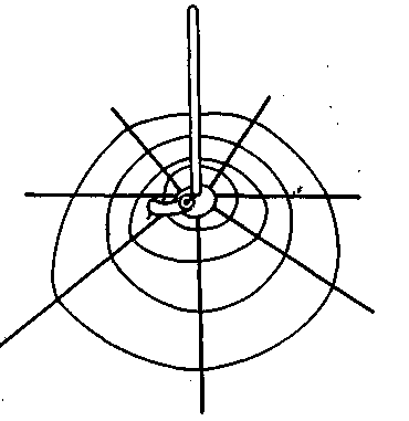
Fig. 3
Counterweights should be isolated from ground. If they will lie on the ground, then from moisture their electrical length is not a resonant antenna. The same must be isolated from earth and their ends. Only in one case can not isolate the ends of the counterweights from the earth: if they are securely connected to the ring-bridge (Fig. 3).
You should never forget that perfect whip antenna has an efficiency of 47%, and the efficiency of the antenna with 3 counterweights - less than 5%. So, operating with whip antennas with three balances of your 200 watts supplied to the pin, 180 watt (!!!) in vain lost, along the way creating a TVI. Many processes in the ionosphere nonlinear, i.e. the reflection of radio waves begins, say, when the input power to the antenna 7 watts, and is already completely not happening at 5 watts. Then you lose the unique opportunities DX QSO, saving on wire for balances.
It should also take into account the distortion of the pattern with a small number of balances. From it becomes spherical radar with the direction along balances. The problem of nding the optimal number of balances has been solved by me with the help of computers. The solution presented in Fig. 4. It can be seen that the minimum required number of counterweights equal to 12. If more efficiency is growing slowly. Counterweights shall be located at the same distance relative to each other.
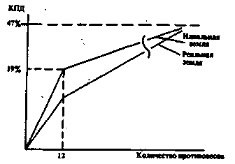
Fig. 4
The angle of their location relative to the pin must be between 90° to 1350. At larger and smaller angles decreases efficiency and PhD distorted. Counterweights must be a minimum length of the core pin. This can be explained by the fact that flowing between the pin and counterweights bias currents occupy a certain volume of space, which is involved in the beamforming. Reducing the length of the counterweight, and, therefore, reducing the amount of space that serves the formation of D. D., we significantly worsen the performance of the antenna. With great approximation we can say that each point on the pin corresponds to a point on the counterweight. However, there is no need to use counterweights longer than the main pin.
The counterweights and the pins should be covered with a protective paint. This is necessary to ensure that the material from which the antenna, not oxidized. Oxidation of vibrators leads to breakdown of the antenna due to the fact that a thin film of oxide has a significant resistance, as well as on HF very pronounced surface effect, the energy transmitter is absorbed and dissipated in the warmth of this film.
It is highly desirable to use radiotrack (the one that painted the locators). Conventional paint contains particles of dye, absorbing RF energy. But, in a pinch, you can use regular paint.
3. The sizes of vibrators, whip
As is known, the radiation resistance of the antenna of the radio isotopic laboratory in proportion to the ratio L/d, where L - the length and d is the antenna diameter. The smaller the L/d ratio, sirokopolosnie antenna and more efficiency.
Note that when using thick impact vibrators "end effect". It is caused by the capacitance between the ends of the vibrator and the earth. Physically this is reflected in the fact that the antenna is obtained "long" design. To reduce usually broadband pins are tapered. The calculations show that the minimum required thickness of balances should be
d=D/2,4 n, where
d - diameter of balances, D is the pin diameter, n is the number of balances.
Often hams can't install quarter-wave pin and use the pin having a smaller size. In principle it is possible to align the pin of any length with matching devices. However, the short pins are low active and large reactance [3] and will be coordinated very suboptimal (themselves matching the device can dissipate up to 90% energy). And if it uses short and surrogate balances, the effectiveness of this antenna system will be very low. However, in the mobile communication often these surrogate antennas are used. But that's only because other types of shortened antennas will work even worse!
4. The directional whip antennas
Many are wondering what impact the lifting height of the pin to its directivity in the horizontal plane and depends on whether the resistance of the height of the suspension. The most important result of [4] is that the current distribution in the pin does not depend on the height of his suspension in the presence of perfect the "ground". Practically this means that no matter what the height of the probe, the resistance will be constant. The overall result of the decision indicates that if the pin is configured to resonate, its lower end may be grounded. Thus it can be fed at any point.
The results of this important conclusion and created the whip antennas (flag-antenna mast-antenna), the lower end of which is connected to "land" and fed via gamma-approval.
Charts directions half-wave vertical plane of the pin shown in Fig. 5. From this figure it is seen that the higher the antenna is, the less steep the angle of radiation to the horizon. This is because the sums emitted by the probe wave and the wave reflected from the ground. If the soil has poor conductive properties, the directional diagram will be close to the radiation pattern of the probe above the ground. To raise the antenna to a height wave length does not make sense, because it does not reduce the angle of radiation, and just beginning to split upper lateral petals.
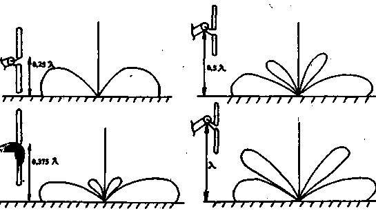
Fig. 5
You should remember another interesting feature of the pins, the height of which is equal to the wavelength or more. Such antennas in professional communication are used as anti-fading [5]. This means that the antenna will receive the signal coming from fading on a pin or a quarter-wave dipole.
5. Coordination whip antennas
For successful work with the whip antenna should be aligned. Despite all the seeming variety of matching devices and pins, they can be divided into 3 groups.
1. Pin agreed, the electrical length equal to a quarter wavelength;
2. Pin with an electrical length greater than desired, the length of the "clean" using the container;
3. Pin length less than a quarter wavelength. The remaining length of the "add" inductor.
It must be remembered that the condenser and coil must be of the highest possible quality, and it is desirable that TKE and TCI were the best. Usually shortening capacity of the capacitor can be in the range of 100 pF 28 - 18 MHz, the parameters of the extension coil units µh to 21 MHz, tens - up to 3.5 MHz.
In conclusion, it should be noted that this practice is applicable to pins with a length that is a multiple of a quarter wavelength.
6. Types of whip antennas
Unbalanced vibrator with a screen of finite size (Fig. 3). This antenna I used mainly Amateurs. As the screen is usually used counterweights length less than a quarter wavelength.
Asymmetrical loop vibrator (Fig. 6). It coincides with B. B. classic pin. However, he has the advantage, reflected in the fact that one end is grounded. The selection of thickness dl and d2, you can change its input impedance in wide range. When d1=d2, the resistance of the vibrator will be equal to 146 Ohms.
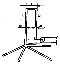
Fig. 6
Resistance single-ended vibrator having a different thickness, is calculated according to the formula (1)/: Ra=(1+n2).36n, where n=ln(d/d1)/ln(d/d2).
Broadband vibrators, are manufactured from thick tubes, pins, and plates. Can be both conical, and orthorhombic, cylindrical, solid and lattice (Fig. 7). The overlap of the range of operating frequencies depends on the ratio of I/O. the lower sirokopolosnie vibrator. Well known antenna UW4HW broadband is asymmetric dipole, and the vertical emitter UA1DZ - broadband symmetrical dipole
.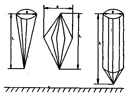
Fig. 7
Conical antenna is a special case of broadband vibrators (Fig. 8).
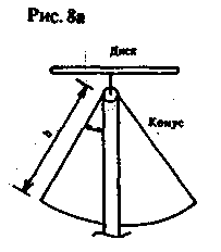
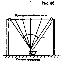
Fig. 8
Radiation field is created by currents flowing over the cone and the disc plays the role of screen and almost does not radiate. When the opening angle of 600 achieved the highest coverage ratio range equal to five, when IPM > 0.5 in a feeder with an impedance of 50 Ohms. The maximum wavelength equal to 3.6 . Directivity discohouse LW antenna and УSW about the same as an ordinary pin. To apply the wire LW variant cone antenna (Fig. 8b), in which instead of the cone is flat wire fan, and instead of disk - grounding system of radial wires.
I would also like to draw attention to the antenna-mast. A special feature of these antennas is that the lower end is grounded.
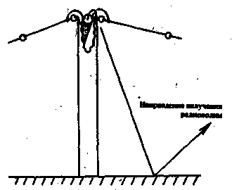
Fig. 9
The top antenna power (Fig. 9) is excited using a feeder installed in the mast. It is fundamentally. B. it is the same as that of the conventional pin, but losses in the radiation and reception more, since the radio wave is reflected from the earth with radiation.
Antenna average power (Fig. 10 is a mast in two parts excited sequentially at points 1 and 2 voltage, which is supplied by a feeder installed in the lower part. The antenna impedance at the feed point Ra=Rb/cos2kll where to - the velocity factor, Rb is the resistance of the "clean" vibrator in point 3. Choosing the ratio between 11 and 12, it is possible to align the antenna with the power feeder. Of fundamental importance is that the feeder should be inside the bottom of the antenna. The lack - difficulties with the insulator for the upper part.
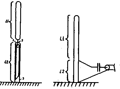
Fig. 10-11
Antenna shunt power (Fig. 11) is excited in parallel with shunt connected to the mast at a certain height 11. Typically, the input reactance of the lower and upper parts of the antenna are respectively inductive and capacitive in nature, and the input resistance at the point 1 antenna equivalent parallel circuit. The selection of size 11 provided the best agreement with the power feeder. The current distribution is such that partially attenuates the radiation of the antenna, so the shunt should make a minimum size. Classical application of shunt power - gamma-approval.
Often, especially when building antennas for low frequency ranges, there is no way to position the vibrator vertically relative to the ground. When the location of the pin is inclined relative to the earth radiation pattern, of course, will be distorted.
Should be placed as much as possible balances under the part of the antenna that is tilted. It is necessary, also, to raise the counterweights so that they form with the antenna angle of not more than 135°. It should be remembered that this antenna is more severe in coordination due to the presence of a significant reactive component.
Literature
Author: I. Grigorov (UZ3ZK); Publication: www.cxem.net


