The correct statement may be erroneous. No pun intended, but a statement fact. Taken out of context correct statement may be entered in misleading if, for example, are not named constraints under which it true. Something like that, in the opinion of the author of this article, has occurred with the popular characteristics of the antenna 6λ/8.
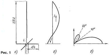
The official borders and ultramarathoning, as well as among the owners of CBS radio is popular vertical antenna length 5λ/8. From Amateur radio literature and advertising it is well known that vertical the emitter length of 5λ/8 gives the maximum pinned to the ground petal chart the directivity in the vertical plane (in a horizontal bar chart pie) and therefore, has a maximum directivity. The simplest version of the antenna depicted in Fig. 1,and. Length 5λ/8 is not resonant, so it is adjusted to Зλ/4 introduction in the painting of inductive emitter element: coil L or a segment of a closed line with an electrical length of λ/8.
"Return" current from the wire's spread on the quarter-wave balances. They do not participate in the radiation, since the currents in them are in the opposite side. Bend the balances down is impossible, as in this case, the electric the antenna length will increase due to the vertical component of the current balances that adversely affect the radiation pattern. Often the lower drawing conclusion inductor is connected to the counterweights. This location is connected braid and center conductor of the cable to the outlet of the coil. In the range of 27 MHz the counterweights are often made shorter than λ/4, respectively, by increasing the inductance for tuning the antenna to resonance.
The current distribution in the antenna shown in Fig. 1,b. It is with good accuracy can be considered sinusoidal. Directional diagram (Fig. 1) has a "zero" under angle to the horizon and unnecessary side lobe under even greater angle. This petal - fee clamped to the horizontal main lobe and mentioned maximum KND. Here, perhaps, is the brief description. what was known to the author ( as with other hams) about this antenna, and caused some... bewilderment.

Haunted the lower portion of the radiator, where the current is directed in the opposite direction with respect to the current in the upper half-wave parts. It is known that directivity is formed as follows: field from each small cut radiator summed up in any direction with regard to their amplitudes and phases. In the direction of the horizon length of paths of propagation of waves from all segments the same and additional phase shift is not. Field plots from the top, half-wave of the aerial phase and add up in amplitude, and the fields from the bottom part (where the current direction is opposite) and antiphase... deducted!
From these considerations, it turned out that shorter - half-wave vertical the emitter should work better than the vibrator length 5λ/8. But if the direction the current in the lower section of the radiator length 5λ/8 any way to change contrary, he will be more effective. For proof of this conclusion you can either calculate KND theoretically, either put the appropriate experiment. But knowing that this is all a long time ago made, the author chose to study old literature. And what was it?
First vertical antenna-mast length 5λ/8 was described by S. Ballantyne else in 1924 [1]. It was developed as the BC antifading antenna. An additional advantage of this antenna immediately became very popular, was the fact that it really creates in towards the horizon of maximum field strength, but only in the class of antennas with natural (sinusoidal) current distribution along the antenna, located directly above a perfectly conducting surface.
The first part of the statement many of us remember well, but about the second part of the authors of the articles in Amateur literature, apparently a little rusty. The professional is also reported [2]: "If special means are taken to prevent a reversal of currents below the upper half wavelength of the radiator, further horizontal gain can be obtained...". In other words, if you reverse the direction of the current in the bottom of the antenna, you get an additional win in the radiation at the horizon. It is possible to continue increasing the length of the antenna with in order to increase the gain. Recall that the classical antenna length 5λ/8 to increase the length anymore, as it dramatically increases the side lobe charts, and decreases charge.
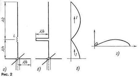
Reversional the current in the bottom of the antenna, it is advisable to increase the length of another λ/8, to get rid of the matching coil. The result will be good known in-phase collinear antenna, proposed in 1911 by the engineer company "Marconi" Franklin. The Franklin antenna is a vertical wire, broken into segments of polvani, between which the coil included (Fig. 2A) or a quarter wave line (Fig. 2,6). In these elements, and "hidden" reverse half-wave current. The currents in the radiating segments are in-phase (Fig. 2), which narrows the chart and significantly reduces the side lobe (Fig. 2,g). The bandwidth of this antenna is a few percent.

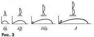
Dynamics of change the directivity by increasing the antenna height and the number of "floors" ( Franklin) illustrated in Fig. 3, borrowed from (2).

Diagrams are shown, again for the case of a perfectly conducting earth. Also the soil under the antenna to the conductors or dielectrics can calculate the tangent of an angle losses (the ratio of conduction current to displacement currents): tgδ = jnp/sm = δ/ωεε0. Among the conductors he has a lot more units, and dielectrics lot less. The tangent the loss angle is frequency dependent. The same soil will be close to the conductor when work on medium wave, and the high frequency SW bands and УSW (the required range of frequencies!) will be the dielectric. And this will change the phase reflections from earth return, and towards the horizon will no longer high beam and low. Main lobe diagrams orientation in this case detaches from the surface and goes under some angle to it (the smaller, the higher above the ground mounted antenna).
In other words, when working on a conducting ground antenna 5λ/8 really surpasses half-wave dipole. This can be explained by a narrowing of the chart orientation due to the fact that the main radiating portion is located above surface and compensates the decrease of the field due to radiation from the bottom. If the antenna 5λ/8 is located in an open space, such compensation not gonna happen, its advantage disappears in front of a half-wave dipole. It is written in less applicable to high-rise antenna systems composed of УSW antenna length of 5λ/8. Spanning a greater distance the basic, half-wave emitting segments, as in the case of the conducting earth, narrows the chart and compensates for the loss from radiation areas with reverse current. But in this case exception "return" sections should give a prize.
It is not known whether there had been disputes between Ballantyne and Franklin about the merits of their antennas. Probably not. since the antenna was designed for a completely different goals. But among radio Amateurs such disputes arise repeatedly. I hope what the article points will help in these disputes supporters of common-mode antennas. But the practical conclusion reached by the author of these lines, next. If you decide to make a vertical Omni-directional antenna and have the the opportunity to make its height greater than λ/2, but less than λ, the greatest the positive effect will not receive antenna "five-eighths lambda", and with antenna Franklin (see figure 2).
Literature
Author: V. Polyakov (RA3AAE)


