Among the variety УSW antennas used for Amateur radio communications [3, 4], a special place is occupied by "the wave channel" with a long traverse (boom), as the most simple to manufacture, is not critical to setting, allowing to obtain high gain and good directivity. Furthermore, you can create complex high-performance antenna-feeder system for making QSOs via the moon.
In table. 1 shows the main characteristics of the most common "wave channels" on a two-meter range. As can be seen from it, there is a tendency of improvement of the antenna parameters with increasing length of the beam. A significant difference in the ratio F/B (forward/backward") caused the use in some cases of complex reflectors.
Table 1
Antenna
The length of the boom, m, (part of the wavelength)
Gain, dB
Chart orientation, radius, in the plane
The ratio F/B, dB
The author of the development
E
H
DJ9-2-1,8
3,75 (1,8 l)
11,2
39
44
20,2
DL6WU
TONNA-13
4,42 (2,13 l)
To 11.35
36,3
40
17,5
F9FT
DJ9-2-2.1
4,44(2.1 l)
11,8
36,8
40,5
24,2
DL6WU
YU0U
2x3,63 (3.5 l)
11,95
37
33,5
33
YU0B
TONNA-16
6.34 (3,1 l)
12,65
34
37
21
F9FT
TONNA-17
6,545 (3,2 l)
12,9
33
35,7
30
F9FT
DJ9-2-3.2
6,69 (3,2 l)
13,25
31,2
33,5
20
DL6WU
TONNA-17
6,545 (3,2 l)
12,9
33
35,7
30
F9FT
DJ9-2-3,6
7,5 (3,6 l)
13,6
30
31,75
20,8
DL6WU
DJ9-2-4,0
Of 8.34 (4,0 l)
14
29
30,5
24,3
DL6WU
LBX-16
8,509(4,1 l)
14,05
28
29,5
22,6
DL6WU
DJ9-2-4.4
9,18(4,4 l)
14,3
28
29,5
21
DL6WU
LBX-17
9,35 (4.5 l)
14,4
27
28,5
20
DL6WU
DJ9-2-4.8
10,02 (4.8 l)
14,6
27,5
28,8
22
DL6WU
All "the wave channel" on УSW ranges on the way to the location of elements on the traverse can be divided into three types: they can be electrically connected with a metal boom, isolated from him, or be placed on non-metallic boom. Each kinds have their "boom effect" - the degree of influence of the diameter of the boom in the electrical length of the pass-through element. The required geometric element length not only depends on the diameter of the boom, but also on the diameter of the element. After the publication of K. Fechteler description antennas "TONNA" (F9FT) in the magazine "Radio" [5] many ultramarathoning former USSR repeated these designs, for a long time which became a kind of standard УSW antennas. Apart from the ease of manufacture of these designs have a number of significant fundamental flaws. First, the lack of alignment and balancing questioned the possibility of obtaining a "clean" chart napravlennosti. Secondly, the elements placed on the boom, electrically connected with the latter. Any mechanical connection does not guarantee long-term reliable electrical contact of heterogeneous metals, even aluminium, duralumin). The lack of contact element-boom or its unstable nature leads to a change of the antenna parameters (increase of the CWS. the distortion diagrams, noise). Third, if at hand are no materials on the boom and the elements are completely relevant to the description, the use of random material does not allow to obtain the expected results.
The proposed design DJ9BV antenna is free from these disadvantages. In table. 2 shows the main geometric dimensions of this antenna, it R stands for reflector, DE-vibrator, D -Director.
Table 2
Item
Length,
mm
The distance between
elements, mm
The distance from zero
mark, mm
Note
R1 R2..
1083
-
0
Double for 4.8 l
R1 R2..
1053
-
0
Double for the 1.8 l to 3.2 l
R
1030
-
0
For the 2.1 l and 3.6 l, 4l, 4,4 l
DE
990
360
360
Vibrator dia. 8 mm
D1
950
165
525
D2
940
375
900
D3
930
450
1350
D4
920
525
1875
D5
915
585
2460
D6
910
630
3090
D7
905
660
3750
DJ9-2.1.8
D8
900
690
4440
DJ9-2-2.1
D9
895
720
5160
D10
890
750
5910
D11
885
780
6690
DJ9-2-3.2
D12
880
810
7500
DJ9-2.3.6
D13
875
840
8340
DJ9-2.4.0
D14
870
840
9180
DJ9-2-4.4
D15
855
840
10020
DJ9-2-4.8
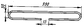
Antenna length is 2.2 l and 3.6 l, the 4.0 l and 4.4 l have a single reflector, 1.8 l, 3,2 l, 4,8 l - double reflector that increases the ratio of radiation. The boom is made of duralumin profile of square section sizes HH mm. Elements are made of 4-mm-thick duralumin rods. The vibrator is made of aluminum tube outer diameter of 8 mm and a wall thickness of 1 mm. Design of the active vibrator shown in Fig. 1. Mid-point of the vibrator may be electrically connected to the boom.

Fig.1
Matching U-knee are made of cut length 680 mm coaxial cable with a characteristic impedance of 50 Ohms. Special attention should be paid to the reliability of the waterproofing of the connection node of the vibrator with the U-elbow and feeder.
The design of the vibrator, with the resistance of 300 Ohms, is described in [6].
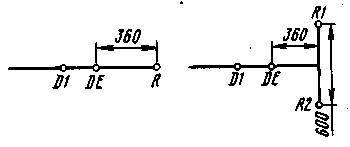
The placement of the reflectors shown in Fig.2.

Fig.2
When the diameter of the boom more than 20 mm the length of all the passive components should be increased by 1 mm with a diameter of 25 mm by 3 mm - 30 mm, 6 mm - 40 mm. as amended for the length of each boom element may be made of pipes of different diameters. The use of the telescopic boom increases the mechanical strength of the structure. If the diameter of the passive elements is 5 mm, the lengths of all elements must be reduced by 4 mm. Passive elements must be reliably isolated from the carrier traverses.
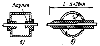
Accommodation options elements shown in Fig.3.

Fig.3
In Fig.3,a given variant DJ9BV, in Fig. 3,b - RW3TJ. In the first case used the standard nylon bushings with a hole diameter of 4 mm are used In the second 5-mm elements and pieces of tubing of stabilized polyethylene (sheath coaxiale cable RK75-4-12).
The electrical parameters of different variants of antennas at the frequency 144,5 MHz at SWR no worse than the 1.2 and table shown. 3.
Table 3
Antenna type
Gain, dB
The ratio F/B, dB
Radiation pattern, degrees
The distance, m, in the plane
E
H
E
N
DJ9-2-1,8
11,2
20,2
39
44
3,10
2,77
DJ9-2-2,1
11,8
24,2
36,8
40,5
3,29
3
DJ9-2-3.2 m
13,25
20
31,2
33,5
3,86
3,6
DJ9-2-3,6
13,6
20,8
30
31,75
4
3,79
DJ9-2 4,0
14
24,3
29
30,5
4,14
3,94
DJ9-2-4,4
14,3
21
28
29,5
4,29
4,07
DJ9-2-4,8
14,6
22
27,5
28,8
4,36
4,17
In columns "the Distance E and the Distance H" indicated an optimal distance between the antennas in the vertical and horizontal planes in the manufacture of antenna arrays. The size can be changed in the range from 80 to 105% of the specified in the table. Downsizing allows you to improve the radiation pattern and gain - to increase the gain. Four antennas DJ9-2-4,0 capital gain +5,9 dB relative to a single, the total gain of this antenna is 20 dB.
The author of the article manufactured and tested four DJ9BV antenna design. Antenna DJ9-2-3.6 for a long time operated on the radio UZ3TXB, was used in expeditions UW3TJ/A and RU1R. Antenna DJ9-2-4,4 showed excellent results in the expedition UA1C, allowing the team УSW Committee of the CPP to show the best result in the contest "ARIA-93".
The author expresses deep gratitude DJ9BV for the kind permission to use the results of his work [2] and was confident, chno this publication will allow ultramarathoning to manufacture high-performance antennas and antenna systems.
Literature
1. Gunter Hoch (DL6WU). Extrem lange Yagi-Anicnnen. - UKW-BERtCHTE. 1992, N 1.
2. Rainer BcrlelmeBter (DJ9BV). Yagi-Antennas for 144 MHz.-DUBUS. 1990. N 1.
3. Spindler. Wireless antennas. - VEB VERLAG TECHNIK BERLIN, 1981.
4. Bieńkowski Z., E. Lipinski Amateur antenna short and ultrashort waves. - M: Radio and communication. 1983.
5. Fechtel K. (UB5WN). Highly effective УSW antenna. Radio, 1983, N 3.
6. Kharchenko V. (RB4EXN). Vibrator DJ9UV-1-ONG-YAG1. Amateur radio operator. 1991, N 6.
Author: Oleg Arkhipov (RW3TJ), Nizhny Novgorod; Publication: N. Bolshakov, rf.atnn.ru


