Any radio Amateur, especially a beginner, getting to the manufacture of the antenna "wave channel", immediately faced the challenge of how to translate most accurately in metal all sizes. The manufacturing accuracy should be quite high for the range of 144 MHz- ±1,5 mm range for 432 MHz - ±0.5 mm
More precisely executed than the antenna, the options will be higher is Not conducive to high-quality manufacturing of the antenna and a conventional home with a set of plumbing tools -drill, scissors and a hacksaw And yet, I claim that having this minimal set of tools, it is possible to accurately make the antenna even with a long traverse Is checked in the manufacture of multiple antennas DJ9BV -13 elements on 144 MHz and F9FT - 21 elements on 432 MHz. They all turned out with high accuracy.
The minimum required tools.
- hand drill (mechanical) - its better "feel";
- a set of drill bits with a diameter of 2.5 mm 2 with l=69 mm l=50 mm,
- hacksaw with very small teeth (such is better for cutting thin-walled tubes),
roulette 5 m (preferably -10 m) - two improvised conductor (IC).
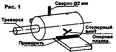
Additionally, it should set "field", which can be a piece of smooth rail channel suitable length of the IC is shown in figure 1, it is made as follows. Taken two segments of the rental (circle or hexagon) with a diameter of 50...55 mm l=80 to 100 mm with smooth ends, and on a lathe drilled axial hole, the diameter of which is 0.5 mm larger than the diameter of the beam. Be sure to check freely along the entire length of the traverse are billet

Maybe the pipe will traverse somewhere slightly dented, then a gap of 0.5 mm have to be increased to 1 mm, or a mallet to beat them the pipe. If the workpiece along the traverse were free, it is welded in the center of the support strips 120.. 150 mm To the weld in the middle of the UK need to drill and cut thread M6 8 mm for the locking screw.
The screw should have a comfortable handle and be sure to taper the end. Only this screw provides a clear and soft fixation of the conductor on the traverse to the right place.
Next you need to drill the machine (Important! Ensures accurate perpendicularity to the axis of the conductor) to drill two holes diametrically, stepping 20-25 mm from the edge. Must be drilled through one side of the conductor and the second half. One hole is working, the second is a spare.
In any case, to start and finish marking one traverses only need one hole. When both conductors, you can begin the markup process. In this work desirable roulette whose length is greater than the beam size. If the markup to make roulette several times, inevitable error in size. So the markup should be done at once. Before the markup, I'll make up a table of distances from zero in millimeters, i.e. from the left end of the traverse. Point R (reflector) corresponds to the value "0" mm. When marking crosshead need two helpers. The assistant on the left accurately captures "0" roulette for cutting the pipe. The assistant provides the tension to the right roulette along traverses. Keen-pointed Scriber on the pipe are risks in accordance with the table. The risks are small but clear, must be applied precisely against own division and only once,across the pipe.
After marking beam on the ends of the wear conductors (figure 2). The right to establish approximately a meter from the end, and is fixed with a stopper. And the left is exactly flush with the edge of the pipe, and also fix the stopper. Now a hand drill with a drill bit that drilled the conductor (2 or 2.5 mm) from the top, using the UK as a guide, drill through the yoke. Try to keep the drill exactly vertical and not much to click. First bored through the upper wall of the bar, and then lower. Hit the end of the drill to the bottom of diametrical holes. SC ensures that you drilled exactly perpendicular to the axis of traverse. Next, release the stopper of the left SC and move it to the right until precise alignment of the left side of the IC with the following mark. Fix the conductor stopper and drill the second hole. This will provide the exact location of the active vibrator. Again we turn on the stopper of the left SC, and move it to the right to match the left side with the next label. So consistently moved left riser and right to the middle of the bar, not touching the right SC.

And so, when the drilled hole under the fifth Director of the (approximately), hold the stopper of the left SC (important!), Unscrew the stopper of the right SC, shoot it from the right end of the bar, be moved to the left end and secure it with a retainer. T to the "field" where were moving conductors, smooth (we agreed in advance), then upon further movement of the left SC right until the end and drilling under the other Directors all holes are exactly in the same plane and perpendicular to the centerline. Is performed and the second requirement all elements strictly in one plane.
When marking the holes are drilled, remove the IC and ream hole diameter elements. By doing this work, be careful to drill a larger diameter is not "escaped" to the side. It is better to work with a hand drill. Try to use a short drill bit.
The reflector and Director I produced from an aluminum wire 4 mm in diameter - from the cables from the power lines 10 kV. The rod is somewhat bland (bend from the crows and pigeons), but the antenna even with the use of thin-walled steel pipe with a diameter of 22 mm (like me), it turns out very easy. However, it is sometimes necessary to climb on the roof and align the elements of a long stick with a fork on the end.
Because the items in the F9FT antenna pass through the yoke, I had to think how to fix them there. I mount completed.
Of foam rubber (seal panels in the construction of homes) cut the bars with a length of 50 to 60 mm That is easier to push into the pipe, made them hexagonal, and in the middle inflicted on them in white paint ring band. Cleaning the inside of the yoke from stripes (formed during drilling) and rust, alternately gently drove the posts into the pipe. This requires "ramrod" length somewhat more than half the length of the beam. Picked up the yoke, gently inserted a column rubber and riding straight pipe with "ramrod", drove the bar up to the middle of the traverse.
In the holes for the elements they are inserted, guided by a white ring band. You need to be careful and not miss a single item, otherwise, you will need to disassemble everything. Filling thus one half of the pipe, turn it the other end and repeat all.
After installing all bars are drilled with a drill bit. I got 3 mm depending on the diameter of the elements, you need to experiment. For easier pulling elements traverse through them should be moistened with a damp cloth. Oil cannot be used-rubber corroded over time, and lashing out loosely.
The DJ9BV antenna elements are insulated from the yoke. I would recommend using a solid insulating sleeve. The mount is more reliable if the sleeve is cut along. While pushing the cut of the sleeve through the yoke looks like collet clamp element. You only need to precisely match the diameter of the holes in the boom. I did a sleeve of vinyl tubing with a diameter of 8 mm, and the holes in the traverse were 7 mm.
A few words about how to attach the yoke to the tube of the mast. It is best to perform the fastening of the U-shaped bolts through the steel plate thickness 4...4.5 mm. For greater rigidity, the edges of the plate (top-bottom) is better to bend at an angle of 90°, 4...5 mm. And the studs that fasten the plate to the pipe mast, under the nuts need to put strips of lining thickness of 5...6 mm when tightening the screws the plate is not bent, i.e. to traverse left straight. Drilling pipe traverses the DPJ mounts do not advise it, the wind would snap her in this place.
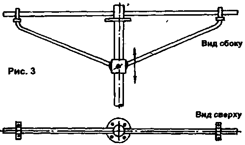
Mounting the antenna on 432 MHz need to do differently, because with the passage of fastening of the pipe through the antenna mast cloth decreases the gain and distorted radiation pattern. My fastening is executed as shown in Fig.3.

Taken a section of pipe l=1 m, the diameter of which allows you to freely enter inside the rotary mast, and one end welded to the Playground. Platform diameter beam antenna is attached. To traverse does not bend, down her back two brace of pipes with a diameter of 14...16 mm; the Struts at the top of polohauai mounted on the traverse, and the lower ends welded to the freely rotating machined ring with two grub screws M8. This design gives the ability exactly without deflection to put the yoke of the antenna, whatever length it may be. After all polygonati are tight, the antenna rises up, and with a stick with a fork on the end is inserted into a pipe mast, placed Parallel to the antenna for 144 MHz and delayed locking bolts on the pipe mast.
Author: G. Kamenev, Cherkessk; Publication: N. Bolshakov, rf.atnn.ru


