Interest to work in the ranges of 144 and 430 MHz in local networks led to a corresponding interest in multiband УSW antennas. Mounted on the same mast and powered by one coaxial cable they allow to significantly reduce the cost of producing them.
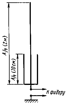
In Fig. 1 shows the structure of a simple dual-band УSW antenna proposed DJ2AZ. It consists of a quarter-wave radiator (GP) on the 144 MHz band, the lower part of which is mounted quarter-wave "glass" in the range of 430 MHz (bottom down, bottom electrically connected to the emitter).

On the 144 MHz band, this "glass" is equivalent to a small inductor in a quarter-wave radiator at the level of the upper edge of the "Cup". His influence is small and the configuration process is compensated by changing the length of the radiator. On the 430 MHz range the length of the upper (above the "Cup") portion of the emitter is 5/8L. The "glass" works in this range as a matching transformer, providing normal power to the top of the radiator.
A possible variant of embodiment of the antenna shown in Fig. 2. It is designed for direct connection to the radio connector PL-259 (standard for many radio stations foreign production). For other installations, the lower part (related to the connector) appropriately modified.
The main emitter compound. The lower part is made of aluminum (preferably brass or copper) rod with a diameter of 4 mm. At its upper end slipped over the tube with an outside diameter of 6 mm and a wall thickness of 1 mm, the movement of which adjusts the antenna. The "glass" is made of pipes with a diameter of 8 mm and a wall thickness of 0.5 mm. At the bottom there is a metal insert through which the position of the "Cup" on the radiator is fixed with a lock screw. In the top of the "Cup" is an insert made of Teflon or any other high-frequency dielectric, which fixes its position relative to the main emitter and eliminates the ingress of precipitation into the "glass".

The diameter of the emitter 4 mm in this embodiment, the practical implementation of the antenna is selected from purely structural considerations - corresponds to the diameter of the center pin of the PL-259 (the lower end of the radiator performs the function of this contact). In other versions of the antenna, the diameter of the emitter , of course, may be different, but then you have to proportionally change the diameter of the tube, forming a "Cup", as well as the top regulating nozzles on the radiator.
"Earth" of this antenna normal: balances on each range (at least three), the metal surface (car roof), etc. by the Way, this antenna can be performed as a normal dipole, consisting of two emitters.
The antenna tuning is performed on a minimum SWR on both bands the selection of the length of the emitter and, within narrow limits, the provisions of the "Cup" on the radiator. We need to start from the very bottom of the "Cup". First, the selection of the length of the emitter antenna set up on the 144 MHz band. Then, by changing the position of the "Cup" that achieve minimum SWR on the 430 MHz range. After that, if necessary, adjust the antenna for the 144 MHz band.
Author: Victor Menzlewski. Mehrbandantennen fur den VHF/UHF Bereich; Publication: www.cxem.net


