


")

In some practical cases, the antenna dimensions comparable with the wavelength, unacceptably large. That is why we have developed electrically shortened (small) antenna. It is also important that the antenna was the only element that emits or receiving electromagnetic energy. One of variants of such antennas, electrically shortened loop antenna is considered in the article. The experiments were conducted at frequencies of 14, 27 and 430 MHz.
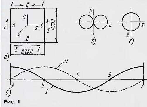
Loop antenna has the best properties when the perimeter covers the largest area, i.e. is a round frame. But for convenience review refer to a square frame and vertical polarization of the emitted (accepted) waves (Fig. 1 (a).
The Directive gain (KND) square frame with perimeter e = λ (λ - wavelength) in free space compared to half-wave dipole is 1.35 dB at resistance rΣ = 100 Ω [1].
Square frame with vertical polarization can be presented as consisting of two half-wave vertical dipoles loaded with all (capacitive load) and posted at a quarter wavelength. Radiation up and down is missing, as the currents in the horizontal conductors of the frame cancel each other out. Distribution the current I and voltage U along the conductor frame is presented in Fig. 1,b. Points A and C, current antinodes are points of zero potential. When connecting the antenna in the gap at point a single dipole is supplied current, and the other at points b and D - anti-phase voltages. The radiation pattern of a frame in the free space in the vertical and horizontal planes, is shown in Fig. 1, g and its shape is close to the radiation pattern of half-wave dipole [2].
Electrical shortening of the loop antenna can be realized by an increase capacitive load dipoles by including antinodes of the voltage, i.e. at the point B and D, the containers, which further changes the phase of the voltage at these points on 180° (Fig. 2,a). Let's call this shortened antenna loop antenna of the two panoramic.
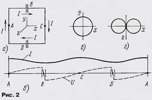
The loop current frame now flows only in one direction (Fig. 2,b), E. the currents in the opposite conductors of the frame are relative to each other oppositely directed. This means that the radiation in the direction perpendicular to the plane of the frame, i.e., the radiation pattern is approximately a circle in a vertical plane and "eight" in horizontal (Fig. 2,b, g). If we consider the analogue of the two antenna a half-wave dipole with opposite equal currents, KND in horizontal plane relative to the circular pattern is 3.8 dB [1].
Thus, this antenna properties are close to magnetic antenna - the antenna with a constant current distribution along the contour of the frame, and radiating predominantly magnetic component of the electromagnetic field in the near zone.
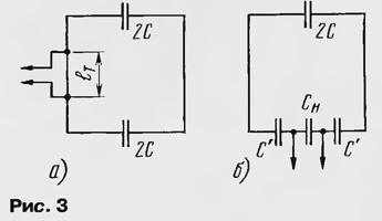
The antenna has four points of zero potential: A, C - antinode currents, (D - mid-distance between the plates of a capacitor - nodes stress. Accordingly, power antenna can near these points. Easier just apply a T-shaped coordination during feeding in the current antinodes (Fig. 3,a) [2] or capacitive voltage divider when connected to a node voltage (Fig. 3,b) [1].
Estimated parameters of the connection circuit can be determined using the following considerations.
- Originally selected frame perimeter e < λ tuned to resonance at the operating frequency f by using two identical capacitors and 2C measured unloaded q-factor of the frame Q.
- The impedance of the loop antenna as LC-circuit RA=1/(2πfC).
- The inclusion coefficient supply line with a characteristic impedance RL at antenna the circuit, based on the condition that when the matching factor of the circuit is reduced twice, K = (PАQ/RL)1/2.
- The distance between the connection points of the T-shaped coordination et= e/K.
- The elements of the capacitive divider SN = COP' = 4·K/(K -2).
- If you connect the supply line to the gap of the frame at point a, the input resistance GVH = Pa/Q.
- The radiation resistance of the frame [3] гΣ = 80π2(2πSp/λ2)2, where Sp is the area of the frame, or round frames гΣ=20π2(e/λ)4.
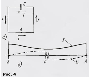
Known another option electrically shortened loop antenna - half-wave dipole with capacitive load, rolled in a frame (Fig. 4,a). For the implementation of this antenna the perimeter of the frame should be smaller than half the wavelength. The point of zero potential of the point A and the midpoint of the distance between the plates capacitor C (Fig. 4,b). Radiation pattern approximately coincides with the directional diagram of the loop antenna of the two panoramic. The connection line power is produced near the points of zero potential, as is done in framework the antenna with two polaramine.
Shortened loop antenna of the two panoramic characterized by more uniform the distribution of the amplitude of the current along the conductor frame compared to the framework an antenna having a continuous frame, so with the same perimeter has a large radiation resistance rΣ and, consequently, greater efficiency ηA (efficiency). The gain on measurement data reaches 3 dB if e/λ = 0,2.
A study of a shortened loop antenna of the two was performed on panoramic frequencies of 14, 27 and 430 MHz.For a frequency of 14 MHz square loop of copper wire with a diameter of 2 mm had a perimeter e = 0,Зλ, capacitance 2C = 22 pF, q-factor unladen frame Q = 100, the radiation resistance rΣ = 2 Ohms, input resistance in the current antinodes GVH = 10 Ohms, efficiency ηA - 0.1 and strip bandwidth of 0.3 MHz. To connect the cable with a characteristic impedance of RL = 50 Ω the capacitive voltage divider comprised of capacitors C = 47 pF and CL = 510 pF, and the length of the conductor frame for T-bar approval еτ = 160 mm. The balancing was carried out using a ferrite ring and a few turns coaxial cable [2]. The antenna was used as a reception room for monitor the operation of Amateur radio stations. In some cases managed to reduce the level of interfering signals due to the symmetry of the antenna, debilitating common-mode interference, and the presence of "zeros" on the radiation pattern.
For a frequency of 27 MHz was fabricated several antennas of two panoramic with perimeters of e =(0,1…0,5)%.. Their study gave the following. The loop antenna radiation resistance decreases greatly with decreasing sizes. It depends in the square from the square (or in the fourth degree from perimeter round frame). Therefore, for the loop antenna with a perimeter e < 0.1 A. the radiation resistance is much less resistance losses, and stripe the transmission antenna is determined only by the parameters of the antenna LC circuit. For loop antenna with a perimeter e > 0.2 A. the radiation resistance becomes commensurate with the resistance losses, the quality factor starts to fall, and band the bandwidth of the antenna and the efficiency increased. In addition, it is desirable the feeding of the antenna to strive to ensure that the Central part of the vibrator, i.e. the current antinodes are free from the connection elements. Therefore, capacitive the voltage divider preferably T-shaped coordination.
Loop antenna for a frequency of 430 MHz was the size 36x22 mm and was made silvered copper wire with a diameter of 1.5 mm. Capacity 2C consisted of tuning capacitor 1…5 pF. Applied asymmetric T-shaped approval. The braided cable with RL = 50 Ω connected to the zero point potential - current antinode, and the Central once at a distance of 10 mm from it. The bandwidth of the loaded antenna is 4.5 MHz, the efficiency-0,05…0,1.
Consider the loop is symmetric, does not require a counterweight, has a point of zero potential (which allows the use of conventional methods power), can adjust the condensers of variable capacity, a little sensitive to the presence in the immediate vicinity of the dielectric and weakly conductive objects, contains no inductive matching elements. When a given perimeter the greatest efficiency has shortened round loop antenna consisting of two panoramic fed through capacitive the voltage divider at the lowest possible losses in the material of the frame and capacitors.
Literature
Author: N. Turkin, St. Petersburg