


")

Intensive study of radio Amateurs УSW ranges over the past two decades has led to the emergence of many various designs of antennas. In particular in recent years received antenna with extended traverse. The length of the beam of the antenna is several wavelengths, and the number of passive elements reaches two dozen and even more. It is often used ultramarathoning when performing long and extremely long ties on УSW through Aurora, meteor showers, satellites and lunar surface.
Interest in antennas with extended crosshead can be explained by the fact that, firstly, at almost the same cost of materials, and to build a normal "wave channel", strengthening them considerably more; second, the design of such antennas is simple, because all elements are mounted on one carrier traverse; third, bribes relative ease of matching the antenna with the feeder, because the RF energy is applied to only one active element. But these antennas and some peculiar disadvantages small suppression of the radiation back and a significant narrowing of the operating band by increasing the number of elements.
A number of interesting designs УSW antennas with extended yoke was developed by the famous French ultramarathoner F. Tonna (F9FT). F9FT antennas have relatively high efficiency, relatively small size and weight, they do not have matching elements. But perhaps their main advantage - easy repeatability, obtaining identical parameters of each individual antenna (in strict compliance with all sizes of elements). The latter allows by compositing several similar antennas to create a complex antenna system with high gain.
The main parameters F9FT antenna shown in the table. Given gain values of the antennas are given relative to a half-wave dipole.
In Fig. 1, and shows a drawing of a 16-element antani for the 2-meter band. Her yoke made of a rental square profile with sides of 20 mm, wall thickness of 1.5…2 mm, or pipe with a diameter of 20 mm. Portion of the bar, where strengthen the reflectors and the active vibrator has the form of a "dovetail" (Fig.1,b). Passive elements are made of aluminum wire Diametro mm. the Use of other materials (copper, brass, aluminum alloy, bimetal) does not cause appreciable deterioration of the antenna parameters, except for its mass. One of possible variants of fastening of reflectors and Directors is shown in Fig. 1.in.
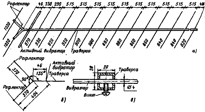
Fig.1
Active dipole with an impedance of 75 Ohms (Fig.2A) are made of aluminum Wire with a diameter of 5 mm, and with a characteristic impedance of 50 Ω (Fig.2, b) of two aluminum tubes of diameters 12 mm, United aluminum shackle-coordinator of wire with a diameter of 5 mm.
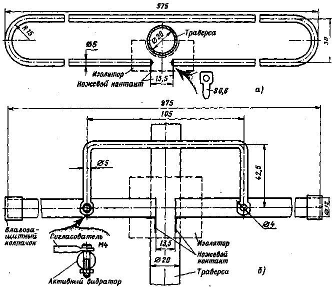
Fig.2
The basic parameters of antennas
Option
9-cell
13-element
A 16-element
21-element
Frequency range, MHz
144 146…
144 146…
144 146…
432 435…
Gain, dB
11,8
12,8
15,6
16,8
Horizontal opening angle, degrees
38
34
32
24
Vertical opening angle, degrees
46
38
34
26
The suppression of the posterior lobe, dB
15
20
22
23
The maximum sidelobe suppression, dB
50
50
60
40
CWS
1,3
1,2
1,2
1,1
The antenna length, m
3,3
4,0
6,4
4,6
Active vibrator must be securely insulated from the yoke. As insulating material may be glass fiber, Teflon, organic glass, etc.
In Fig. 3,a and 3 b schematically illustrates the 9 - and 13-element antenna for 2-meter band. Design of active vibrators with different characteristic impedance for these antennas is shown in Fig. 3 in (75 Ohm) and 3 g (50 Ohms).
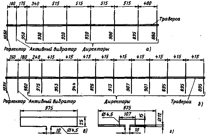
Fig.3
Some difference in the size of the active data vibrators from those applied in a 16-element antenna, driven by the desire to better align the antenna with the feeder. The cross section of the carrier beam of these antennas is the same as for 16-cell (20x20 mm). Structurally, 9 - and 13-element antenna perform as a 16-element.
In Fig.4,a schematic drawing of the 21-element antenna for 70 cm band the Distance between elements shown in the illustration refer to the case of use of a feeder with an impedance of 75 Ohms. When powered antenna 50 Ohm cable distances shall be as follows: the reflector of the active vibrator - 139 mm, active vibrator - Director 1 - 48 mm, Director 1 - Director 2-68 mm, Director 2 - Director 3 - 182 mm. the Rest of the Directors have at the distance indicated in the figure. For cross member using a rental square profile with sides 16.5 mm (you can apply the tube diameter 16…17 mm). All passive elements are made of aluminum wire with a diameter of 4 mm and strengthen directly on the traverse (see Fig.1). Active vibrator (Fig.4,b), are made of aluminum wire with a diameter of 5 mm. At the place of attachment to traverse it needs to be insulated from it.
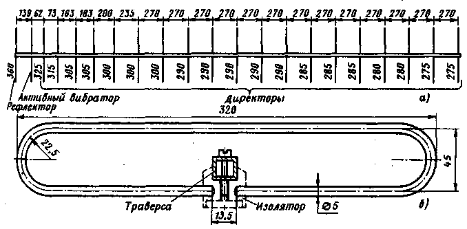
Fig.4
At first glance it may seem that direct nutrition dipole unbalanced coaxial cable may not give good results, as in this case, the ratio of the voltages at its ends is approximately 2:3. And this will inevitably lead to the formation of radiation with vertical polarization, thereby deteriorating the antenna gain and directivity. However, the experiments show that nourish the antenna as possible, but the input impedance of the active vibrator must be matched with a characteristic impedance of the supply feeder and the active element is securely insulated from the yoke. Almost all input RF energy is emitted by the active vibrator into the surrounding space, and a large number of passive elements quite well forms the main lobe of the radiation diagram of the antenna is strict on its axis. In Fig. 5 and 6 shows the directivity pattern in the horizontal and vertical planes 16-element F9FT antennas for 2-meter band.
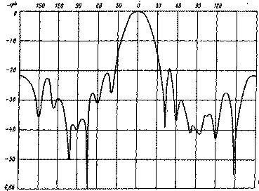
Fig.5
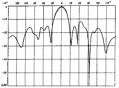
Fig.6
To get more gain. the same type of antenna are combined in the system. When doubling the number of identical antennas, the gain of the system may increase by 2.5 dB. The maximum value is achieved only if the optimal distance between the antennas and the strict phasing of the past. The optimal distance for the 16-element antennas for 2-meter band and for 21-element antenna range 70 cm is 2l. In Fig.7 shows the layout options antenna systems.
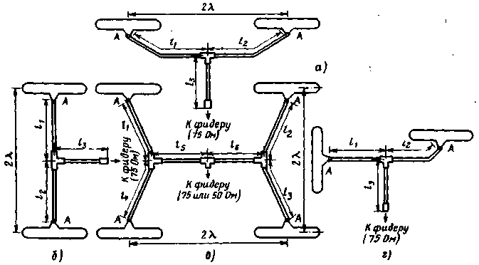
Fig.7
If, for example, are required to coordinate with the supply feeder having an impedance of 75 Ohms, the antenna system comprising two antennas with an active element whose characteristic impedance is 75 Ohm, it is necessary to do the following. Vibrators antennas connected via a tee lengths of coaxial cable (impedance 75 Ohm) with length a multiple of l/2 (l1=l2=спl/2, where n=1,2,3, .... with the velocity factor of the cable), with a quarter-wave transformer of the Latter are made of coaxial cable with a characteristic impedance of 50 Ω the length of the CL/4.
For proper phasing of the antenna system of the Central conductors of coaxial cable segments connected to point a (see Fig.7).
Very easy to align four of the same type of antenna (see Fig.7). In this case, using the stretch of the cables with the same volnovye impedance (50 or 75 Ohms) length l1=l2=l3=l4=спl/2, l5=l6=CL/4.
In Fig.7,g shows an embodiment of unification of the two antennas, which is obtained radiation pattern with circular polarization. Such systems are appropriate to use when working through Amateur radio satellites, as well as when receiving signals reflected from the lunar surface. Both antennas are mounted mutually perpendicular to one traverse, the vibrators of the same name strengthen as close as possible to each other.
For approval use segments of coaxial cable with volnovye 75 Ohm (l1=сп1l/4, l2=сп2l/2, where I1=1, 3, 5,…; P2=1,2, 3,…, l2-l1=l/4) and 50 Ohm (l3=CL/4).
This antenna system with circular polarization has the gain the same as a single antenna.
In conclusion, some practical advice. For convenience and quick Assembly of antenna systems it is recommended that the sections of the cables agreeing to supply high-frequency connectors types SR-75 and SR-50, and for their connections to use HF tees. These knots are easy to protect from the effects of precipitation. If these connectors are not, the segments of the cables can be neatly soldered, and the connection of the cover with polystyrene or epoxy resin. All mounting screws are preferably placed on the lower side beam and to fill their Tube elements with ends closed with nylon caps or rubber stoppers. Where you connected the cables to the vibrators are preferably placed in plastic cups. So long beam does not bend, they can in the usual way to back diagonal rods. The last should be the same length for all of the antennas are arranged in the system.
Literature
Publication: N. Bolshakov, rf.atnn.ru