


")

In the UHF band (DCV) recommended high-efficiency antenna with sharp directivity for the following reasons. High directivity antennas significantly increases the energy potential of the communication line that allows you to either increase the range or decrease the transmitter power. The latter is beneficial not only economically, but also because in DCV range is difficult to obtain high power transmitters.
In addition, when the high directivity of the antennas decreases the possibility of exposure to the receptor interruptions. Finally, highly directional antennas reduce the mutual influence of several closely spaced communication systems operating in the same frequency range. The gain of the antennas directly related to its directional properties, V. certain extent compensates for the loss of high-frequency energy distribution on the communication line. By increasing the distance between the correspondents decreases the level of the transmitted signal and there is a need to use more directional antennas. Such antennas can be built by integrating the system (lattice) multiple antennas with a relatively weak orientation. Single antenna included in the grid should be placed relative to each other at the optimal distance, given their directional properties.
When the distances are less than optimal, the antenna in the lattice will be underutilized and the Directive gain (KND) of the lattice will be less possible. Distances more optimal impractical, as in this case, unnecessarily increased the size of the antenna device as a whole and deteriorating its directional (main lobe narrows and grow side). Roughly to choose the distances between the individual antennas of the lattice is possible, using the concept of effective surface Eff single antenna with KND=Do.
Eff=(Dol2)/4p;
where l is the wavelength.
Introducing conditionally that surface in the form of a square with side a=l/2Sqr(Do/p), it is possible to arrange the electrical centers of the antennas in the lattice on top of a square of side "a". Thus the effective surface Raff antenna array will be approximately equal to n*Eff, where n is the number of antennas included in the lattice. It is obvious that the value of the directivity of the antenna array depends on the values of Do (KND each single antenna) and the number of single antennas, forming a lattice. If you increase this number increased technical difficulties in the in-phase power to the antennas of the lattice and to reconcile it with the feeder. Reducing the length of the working wave exacerbates these difficulties and in the considered frequency range, they are already very noticeable. The essential point in constructing a multi-element antenna array is the element - single antenna. This element should be structurally simple and have aperiodic properties. The latter quality is especially necessary when performing antenna array in Amateur conditions when it is difficult to make a large number of single antennas with high identity. The lack of a single antenna pronounced resonant properties allows without too much damage to the lattice in General, to deviate from the specified dimensions when performing parts of antennas. As this element may be used a zigzag emitter depicted in Fig.1. This illustration shows the dimensions of the emitter on the frequency band 430-440 MHz.
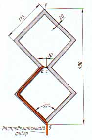
Fig.1
The emitter is made of eight same solid metal plates, fastened together by any method (soldering, bolts or rivets). When fastening bolts or rivets at the feed point of the antenna a - and you need to install brass tin-plated petals for soldering feeder. With this structure, the emitter in the points b-b will be antinode of current and, accordingly, zero voltage. Thanks for the points b-b emitter can be fixed with metal uprights to the reflector, and spend one of these points of distribution feeder without disturbing the electrical symmetry of the antenna. Thus, there is no need to manufacture and use any special balancing device. Distribution feeder from point "b" having a zero potential, is laid on the two plates of the radiator to the points of power where soldered to it. The radiator was stronger than that between the points a-and you can put dielectric charge.
The simple design of the radiator allows its multiple manufacturing with high identity. KND and IPM (coefficient of traveling wave) of the emitter depends weakly on frequency, within the operating range of the waves practically do not change. Thus, the design of the radiator and its aperiodic properties meet the requirements of the element antenna array. The next step in the construction of the antenna array is the placement of elements in the lattice and the choice of the distances between them. The directivity in the E and H planes of polarization of a zigzag tube with a reflector in a predetermined wavelength range is almost the same. This allows you to place the elements of the lattice with vertices of a square with sides approximately equal to 0.9 l. For the successful operation of the antenna array must be properly nurtured and agree on the elements of the lattice with the main feeder. While it is desirable that the power supply system provided synphasicity radiation elements in the lattice and equality supplied to them capacity. The principle of operation of the power system used in the described antenna array can be derived from Fig.2.
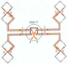
Fig.2
This figure shows four zigzag emitter conductors which are excited in phase from feed points b-B. In this case, the distribution feeders 1 and 2, 3 and 4 are included in pairs in parallel and the pairs themselves at points in-in - in series. This allows a first approximation at points in-in to restore the values of input resistance available at the input of each individual distribution feeder and thereby ensure the same degree of harmonization feeder, feeding four emitter, which has a feeder that feeds a single emitter (IPM~0,6-0,7). Phase of the voltage supplied to the power points in-in, shifted relative to each other by 180°, therefore, for proper phasing of emitters, it is necessary to artificially create an additional phase shift of 180°. This shift can be realized, paving, for example, the distribution feeders 1 and 3 on the right-hand sides of the emitters, and the feeders 3 and 4 respectively on the left. Naturally, the electrical length of the distribution cables from the power outlets in-in points to power the emitters a-a must be the same. In Fig. 3,and shows the structural performance of installation coaxial cables four distribution feeders in the node A.
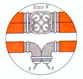
Fig.3.and
Connecting the cables to the node A very simple and additional explanations are not needed. It should be borne in mind that the length of the connecting wires should be smaller, and the seats of adhesions extremely accurate. Node a is mounted on a dielectric Board, which need to 40-50 mm push back from the mast. As the main supply feeder four emitters can be rented as a coaxial 75 Ohm cable (best RC-3), and 300-Ohm two-wire line. In the first case the cable needs to be connected to the points of power - through balun device, a General view of which is shown in Fig.3,b.
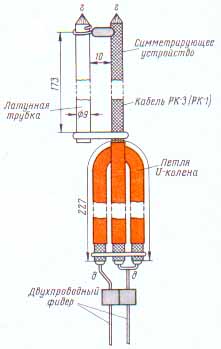
Fig.3.b
This device consists of two conductors of equal diameter, short-circuited at a distance of 173 mm from the point of connection of the Central conductor of the cable. The role of one of the conductors of the balun device performs a braid main feeder, while another uses a brass tube. Points g-g balun device connects to the points-to node A. the Conductors of the balun device must be secured to the dielectric Board power supply node And to the mechanical force from the feeder was not transferred at the point of excitation and does not violate them in contact. When the main feeder uses a two-wire line with a characteristic impedance of 300 Ohm balun to the another device connects U-knee (Fig.3,b bottom).
When the feeder cable RC-3 or RC-1, insert the U-knee is not necessary. U-knee increases to four times the values of the resistors, providing as necessary in the case of the two-wire line resistance transformation, and balancing. Two-wire line with a characteristic impedance of 300 ohms can be made of copper wire. For fixing wires of the line they should be fixed columns, cut from a polyethylene cable insulation RC-3 small pieces with a length of about 10 mm. Pieces of insulation, put on wire line, are fastened together in pairs by an insulating tape (Fig.4).
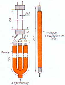
Fig.4
The end of the two-wire line before entering the house should be at the points d-d to connect to another ET-knee, as shown in Fig.4. The device and the dimensions of the antenna array of four transducers, which diagram is shown in Fig.2, shown in Fig.5.
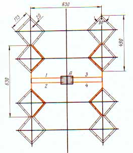
Fig.5
KND of the grating 40. The frame on which the emitters are shown in Fig.6. It consists of four horizontal and two vertical rails mounted on the mast.
Fig.6
If the emitters are made of sufficiently rigid material, the vertical slats can not do. To increase the directivity of the antenna array it is advisable to use a reflector. One embodiment of a reflector is presented in Fig.7.
Fig.7
It consists of two horizontal rails, the edges of which are mounted two segments of the antenna cord or bare copper wire with a diameter of 2-3 mm To the antenna cords (or cables) attached transverse conductors with a diameter of 0.5-1 mm, which form the wall of the reflector. The reflector is fixed on the mast by means of two brackets (Fig.7). It needs to be easier. General view of the lattice of the four radiators with reflector shown in Fig.8.
Fig.8
When installing the grille should definitely send it to the correspondent. Guy wire mast must not cross, and especially to touch the conductors of the radiators of an antenna array. If take-down pass in front of the blade antenna, they should consist of several parts with insulators between them. The distance between the insulators should be of the order of 150 mm. Wire two-wire lipni can be parallel to the mast, but they are not supposed to touch. In excess places they can be fixed on insulators. However, you must strive to ensure that the conductors of two-wire line when attaching and bending (preferably smooth) were not severely deformed. For example, they cannot entwine around the insulators, as is done with wires lighting. As can be seen from the figures, the dimensions of the antenna array of four transducers are relatively small. Is possible to increase the directivity of the grating to approximately 150-160 by further Echeverria.
The selected scheme of power grid elements can do it without much difficulty. In Fig.9 shows the power circuit of the antenna array of 16 elements. It is similar to the circuit of Fig.2, if you count each of the four emitters as a single element. All nodes Fig.9 food outlets in-in and in'-in' is performed as shown in races.3. Dots in'-in' can be connected as the main feeder 75-Ohm coaxial cable from the balun device and a two-wire 300 Ohm line, with the use of CT-knee. Installation of power lines requires special attention, as incorrect connection of the ends of the balun device in any of the power supply units will cause razgazirovanie entire antenna array. The scheme of connections of the distribution cables to the outlets themselves zigzag emitters in fours also shown in Fig.9.
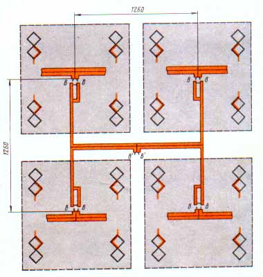
Fig.9
To mount the bars of the 16 emitters on the frame as shown in Fig.10. There is also a vertical rack is not needed. The reflector antenna is performed as described above.
Fig.10
The requirements for feeder systems are fully preserved. Increases demand for careful alignment of the system and its mechanical stiffness. The antenna has a relatively high directivity. Angle of aperture of the radiation patterns at the level of half power is about 16°. Consequently, an undesirable deviation from the direction to the reporter and in elevation greater than ±4°.
Author: K. Kharchenko; Publication: N. Bolshakov, rf.atnn.ru