The vertical antenna to low-frequency ranges are of considerable height, which makes their installation in Amateur conditions. The proposed option of bringing the GP height to acceptable levels is not devoid of originality and will help the hams for a new approach to the design of antennas.
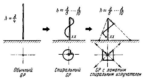
The antenna, which will be discussed in this article, is an intermediate option between a full-sized vertical pin and its shorter version - helical antenna with normal radiation. Here the term "normal radiation" means that the antenna radiates perpendicular to its axis, like the regular GP (unlike spiral antennas with axial - along the axis of the radiation). Such antennas, despite their relatively low efficiency, are widely used in wearable УSW radio stations and shortened SW/УSW antennas for mobile communication. Unlike classic spiral GP is that the proposed antenna has only one spiral turn, which allows approximately two times to reduce the height of the GP, without losing efficiency significantly. In practice, volumetric spiral turn for LW bands to make difficult, but you can replace the "broken helix" (Fig. 1).

Fig.1
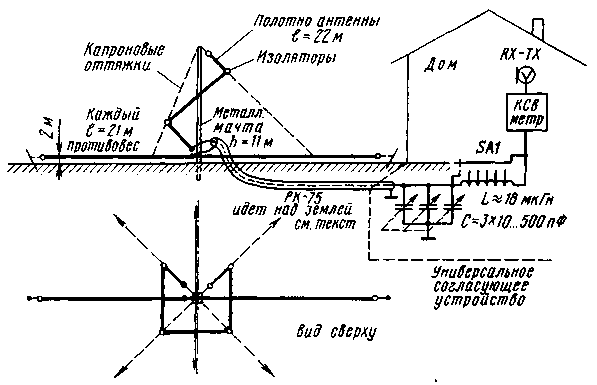
These ideas were tested on the antenna range of 80 meters (Fig. 2). The length of the selected emitter 22 meters. His painting represents one round of "broken helix" with a pitch of winding of 0.1 l and a nominal diameter 0,04 0,06...l. The antenna and its two counterweight (21 meters each) made of improvised cord with a diameter of 2.5...3 mm (multiple twisted wires PAVO,5mm).

Fig.2
The antenna is installed directly at the earth's surface. Its radiation pattern in the horizontal plane is nearly circular. The angle of maximum radiation in the vertical plane is 25". Form isolated from earth balances (their length is not less than 0.25 l) can also be curved. This may somewhat alter the radiation pattern.
The antenna is fed with 75-Ohm cable length 11m, laid above ground at a height of about 2 m.
To get close to one of the CWS between the power supply and the transmitter is on a matching device. Three section variable capacitor with air dielectric - from the old tube radio. Switch - slide type 15 provisions.
The coil has 30 turns of wire sew-2 1.1 mm, is wound with a pitch of 1 mm on the frame with a diameter of 45 mm. the Taps of the coils are made every two turns. This device has been successfully used by me for several years with various types of antennas for all Amateur radio bands.
The antenna tuning is carried out by correction of the length of the helical radiator and balances, but when you use matching device it can not do.
The bandwidth of the antenna with matching unit when the CWS is not worse than the 1.9 got about 60 kHz and no worse than 1.2 to about 30 kHz. When you move over a range with a step of 60 kHz and reconfiguring matching device these settings are saved in the frequency band from 3500 to 3750 kHz.
The antenna performance was evaluated in comparison with the "Inverted V".
The test results showed that on the slopes above 1000 km "spiral GP" more effective than "Inverted V". On routes of up to 1000 km was no difference in the estimates of correspondents. On the slopes up to 2000 km, the difference was estimated to be 0.5-1 point on the volume. At distances of 4000...5000 km, the difference was estimated to be 1-2 points. And finally, on the slopes with a length of 8000 km or more, the difference averaged 2 points and above.
Literature
Publication: N. Bolshakov, rf.atnn.ru


