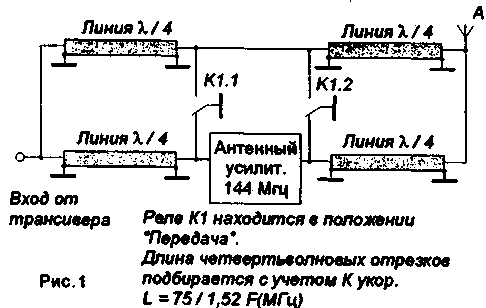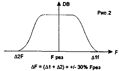
In receive mode on the antenna amplifier and relay winding is supplied voltage. Quarter-wave segments that are connected to the input and output of the amplifier are an extension of the connecting cable and Rin to Rвых equal to the characteristic impedance of the cable do not affect the parameters of the feeder. Quarter-wave segments, designed to "crawl" squirrel-lengths from the antenna and the transceiver have a greater resistance. Their amplitude-frequency characteristic (AFC) is shown in Fig.2.

Thus, in addition to purely insulating properties they possess and filtering properties, being quite an effective filter with steep slopes, due to the high quality factor at the resonant frequency.
In transmit mode the power is removed from the amplifier, and its input and output are grounded, that is almost a full guarantee of protection from the penetration of the RF signal transmitter. In addition, a quarter-wave segments connected directly to the input and output of the antenna amplifier, are notch filters for the transmitter, and the other two cut connected in series, have a length equal to 0.5 lambda and possess property of the transformer resistances of 1:1, without affecting the parameters of the feeder.
The switching relay can be any available. The main requirement for the relay - as the smaller the contact capacity. Good results are obtained by using RES-34, RPA-2/7, etc., with output power up to 200 watts.
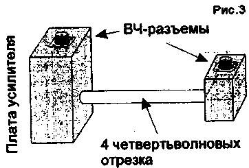
The production version of the antenna switch is shown in Fig.3.

Four quarter-wavelength cable cut, length 342 mm for the frequency 144,1 MHz are placed in a duralumin tube with a length of 340 mm and a diameter of 30 mm. One end of the pipe zavaltsovan in a small box with two high-frequency coaxial connectors (on the right in the figure) separated by a screen. The other end zavaltsovan in a big box (to the left in the figure) in which there are two relays and the power amplifier Board, Fig.3. You should consider requirements for installation of high-frequency devices and be sure to separate the screen from the input circuit output.
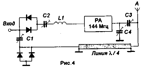
On the same principle, based on the property of a quarter-wave segment is Basileia switching 20 watt power amplifier installed in the car. Instead of high-frequency relay switching diode - anti-parallel connection of silicon diodes CDB, Fig.4.

In the transmit mode, the RF signal transceiver's keys and opens the quarter-wave segment from the entrance RA is short-circuited, and from the antenna has a high resistance. In receive mode the signal strength coming from the antenna, is not sufficient to open the keys and signal through a quarter-wave line segment passes to the input of the transceiver. In a very large signal diode keys serve a protective function.
The power amplifier is assembled on transistors CTA and CTV under the scheme, published in "R-D" No. 1-96.
At its input with manual transceiver is supplied 100 mW and 50 Ohm load would be about 20 watts. The amplifier operates on a shortened quarter-wave magnetic antenna CB range with partly cut upper part extending above the coil.
Author: S. Ksenofontov, ES4BW, Kohtla-järve; Publication: N. Bolshakov, rf.atnn.ru


