For local connections on УSW (including via repeaters) need antenna with circular radiation pattern and a noticeable gain. In Amateur radio practice this problem is usually the use of elongated vertical antennas consisting of multiple emitters, which zapityvat through phasing two-wire line. Very similar model antennas produce many foreign firms, and under different names sometimes are made almost identical model. A typical antenna of this class (for example, model ARX-2B firm CUSHCRAFT) has a gain of 7 dB and SWR at resonance frequency not more than 1.2 (typical). The bandwidth is about 3 MHz. In the horizontal plane of the antenna has a circular radiation pattern, vertical plane of maximum radiation angle is 7 degrees. Usually antennas have a certain margin for adjustments, so when mounting them working the frequency can be varied within wide limits (for example, for the above-mentioned models from 135 to 160 MHz). Such antennas can be made in Amateur conditions.
The antenna design is shown in Fig.1. It is made of aluminum thin-walled tubes and are mounted via an insulator on a grounded metal the mast (total height of the antenna is 4.3 m). The antenna dimensions are for Amateur band 2 meters, with a center frequency of 145 MHz.

Element 1 - tube 890 length and a diameter of 9 mm. At the top of the element 1 installed plug to prevent the entrance of moisture into the antenna. Element 3 - tube length 700, with a diameter of 13 mm. Element 6 - tube 530 length, diameter 13 Element 7 mm. - tube length 380, diameter 16 mm. Element 8 - tube length 1000, with a diameter of 19 mm.
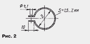
On the upper ends of the tubes 3, 7, 8 made vertical cuts a length of 30 mm, providing a tighter fit of the inner fixed elements. Fixation of tubular elements by using rezhimnyh cable clamp 2, the sketch of which is shown in Fig.2. The design used three threads with inner diameters of D=13, 16 and 19 mm.
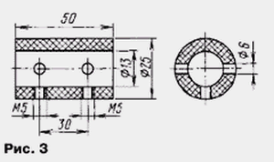
The elements 3 and 6 are electrically connected via a phasing element 5. For this between items 3 and 6 is set insulator, Fig.3. Phasing element is a U-shaped bracket out of aluminum wire with a diameter of 6 mm. At the ends of the tubes 3 and 6, are inserted into the insulator at a distance of 10 mm from the edge, drilled holes with a diameter of 6 mm. screws M5 threaded through the holes in the insulator elements 3, 5 and 6 are fastened together. Length phasing element 5 is set according to the dimensions given in Fig. 1.
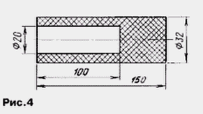
Antenna through an insulator 11 (Fig.4) mounted on a metal pole 17 with a diameter of 32 mm. On the upper end of the mast is fixed (by welding or any other mechanical connection) metal bowl (16) with an inner diameter of 32 mm. In this placed a glass insulator 11. The depth of the Cup 16 is chosen so as the insulator 11 is made from 30 mm.
To items 8 and 16, as shown in Fig.1, with the screws attach metal the corners 13. At the ends of the corners remote from the antenna, drilled one by one the hole diameter of 127 mm of copper wire with a diameter of 5 mm.
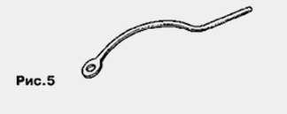
On the corner, attached to the workpiece 16, closer to the antenna socket set 50 Ohm connector so that its threaded or bayonet portion was converted down to the base of the antenna. To the main output connector soldered cut copper wire 12 having a diameter of 5 and a length of 130 mm (Fig. 5).
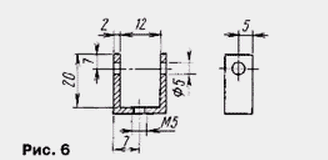
At one end of the wire flatten and drill a hole equal to the diameter of the Central o connector. The wire is bent so as to not touch the antenna, lay down its the opposite end of the element 9. Using metal brackets (detail 10, Fig. 6) and screw M5, located on the bracket, the end of the wire 12 is fixed on the element 9. At the same time, this contact is movable and is used when configuring antenna. Moving to some extent the bracket 10 around the circumference of the ring 9, choose the position at which the VSWR of the antenna is minimal.
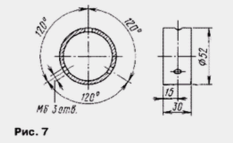
The antenna mast before installing put a metal ring 18, made according to Fig. 7. In this ring screwed three aluminum counterweight 19 length 521 and a diameter of 6 mm. At one end of the counterweight is threaded M6 length 20 mm. Before installing the counterweight into place on the thread wrapped around the locknuts.
To the workpiece 18 with the screw secures the area 13 by analogy with the workpiece 16. Only connector installed here passing. Manufactured separately cable with connectors at the ends and a total length of 1272 mm.
The stretched length of the connected cable set ring 18 and by screwing the counterweights until it stops, rigidly fixed on the mast of the antenna. After that wrap the nuts.
In this article the length of the tubes correspond to the embodiment of the antenna, allows to rebuild its operating frequency over a wide range. For antenna range 2 meters emitters can be unstacked that much easier the design of the antenna.
Author: Alexander Krasnoperov (UA3IAP)


