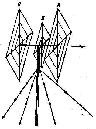
One of the reasons for the popularity of the antenna type "double square" is the ability to create multi-band systems. On each band the antenna has a good figure, high gain and SWR, close to unity. Most hams use the antenna collected on eight spacers of insulating material (hams this design is called "spider").
The operation of such antennas in areas of the USSR with strong winds showed their unreliability. Much more reliable behave "double squares", having a load boom-boom, on which are mounted the elements in the form of a wire framework. Passive frame configured using short closed loops. But this antenna has a major drawback: the distance between the active part and reflectors on all bands equally, and the maximum gain can be achieved only if one of the ranges.

As described below, the antenna does not have this drawback. Based on the antenna "double square" for the range of 14 MHz, and ranges 21 and 28 MHz it is a three-piece. Antenna (Fig. 1) executed on the boom frame is located. angle down. "Double square" for the range of 14 MHz is the optimum distance between the elements is 0.2 lambda, which ensures maximum gain. All three of the reflector are located in one plane (In), frames of Directors on 21 and 28 MHz in the same plane as the active frame on the 14 MHz band (A), and the active frames of ranges 21 and 28 MHz on independent struts in the middle of the boom (B). The distance AB is equal to 165, BV - 260 see Other dimensions of the antenna are given in table. 1.
Table 1
Range,MHz
The length of the sides of frame A,
cm
The loop length of the frame And,
cm
The length of the side frame B,
cm
The length of the side frame,
cm
The loop length of the frame,
cm
14
535
-
-
540
150
21
345
80
355
360
100
28
245
60
265
270
70
Vertical spacers can be made of any material (including metal), horizontal - of insulating material (wood, bamboo, synthetic) or from metal pipes, broken insulation inserts. To power the antennas 14 and 28 MHz feeders applied from coaxial cable with wave resistance of 75 ohms, and 21 MHz 52 Ohm. The feeders are included in the gaps of the lower corners of the active part.. when Balancing this does not apply.
Literature
Publication: N. Bolshakov, rf.atnn.ru


