Perhaps no part of the equipment "lisanova" remains unchanged so as antenna. New transistors and small-sized components allow you to build more sensitive, economical and light receivers, and antennas remain the same, although the weight and dimensions are always an obstacle for an athlete.
In recent years the annular cores high frequency ferrite enable simple means to build antenna arrays with active power of all the elements. It is possible to achieve the same effect that p in the passive antennas, the phase shift of which is selected spacing between elements, by changing the polarity of the transformers.
Below is described the antenna with active power ranges 28 and 144 MHz, built on the principle of in-phase-antiphase of food items. The basis of the antenna is a combination of anti-phase pairs of emitters and dipole. Directivity antiphase pairs of eight. Her EMF changes sign depending on the direction of arrival of the signal. Chart of the dipole (in the plane H) is a circle. The polarity of the EMF of the dipole does not depend on direction. If you fold the E. D. S. antiphase pairs and dipole aligned in space, the total radiation pattern will be odnolistovoy (such as cardioid, if the amplitudes of the two EMF is equal to).
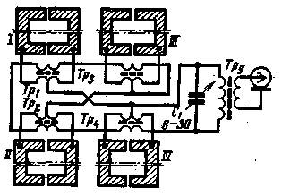
Diagram of the antenna shown in Fig. 1. The antenna elements I - IV and transformers TP1 - Tp4 are included so that are two systems antiphase pairs and dipoles. EMF of each phase pair is removed from the transformer windings, connected in series, and E. D. S. dipoles is between the middle points of the windings. When the washing elements are separated in-phase and anti-phase currents, which, multiplying in the total load (transformer Tp5, and the capacitor C1), give a unidirectional graph. The connection with the antenna is selected turns of the secondary winding of the transformer TP5.

Fig.1
The radiation pattern has two multiplier: cardioid (combination anti-phase pairs and dipole) and eight (antiphase pair). The result is a single petal of a width of 60 and 90° in the principal planes.
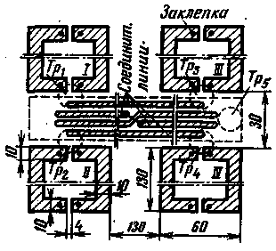
Structurally, the antenna is a sheet of polystyrene or fiberglass, foil on both sides. Elements .antenna I to IV and the connecting lines are made printed media in the form of strips of foil. Strips of antenna elements located on opposite sides of the sheet, are connected to each other at the beginning and end Conductors or rivets. The connecting lines are positioned on one side of the sheet; with his other hand left a wide strip of foil, which is used as a shared bus. Transformers glued with BF directly from the connection area.
These transformers for the range of 28 MHz: TP1 - Tp4 4 and 2X4 loop PELSHO of 0.25-0.3 at the ring of ferrite VC-2 kg 4x2. Transformer Tp5, 12 and 2 turns (stop 70 ohms) PELSHO of 0.25-0.3. The data for the 144 MHz band:
Tp1 - Tp4 1 and 2X1 revolution, TP5-3 and 1 coil.
The dimensions of the antenna are given in Fig. 2. The attachment of the transformers shown by a dotted line. The antenna dimensions can be changed within wide limits depending on design requirements and capabilities, however, it is desirable to observe the specified proportions, These transformers are not critical, if the length of the antenna elements is less than 0.1 to 0.15 lambda.

Fig.2
The antenna tuning is as simple as configuring the resonance circuit TRS. For "deepening zeros", you can enter additional capacitor, placing it between the middle points of the windings of transformers TP3, TP4 or gap in one of the wires connecting the midpoints of the windings. If the selected dimensions differ from those shown in the drawing, it is possible to try to improve the tuning of the antenna switching capacitor between the middle points of the windings Tp1, TP2.
Author: Yu Medinet (UB5UG) Kyiv; Publication: N. Bolshakov, rf.atnn.ru


