Continuing the theme of building antenna systems of base repeaters trunk communication, begun in the 11th and 12th issues of the magazine "Radio" of 1997, I would like to elaborate on this important aspect, as the chart formation orientation (LTO).
The use of vertical collinear antennas makes it easy to get a circular NAM. Such antennas are widely spread in the systems "SmarTrunk-H". However, despite their simplicity, these antennas have some drawbacks inherent cheap designs. These include low mechanical strength and low the resistance to aggressive media. In addition, designers trunking systems often faced with the problem of installing the base of the antennas on the towers farms. Usually all good position already occupied antennas departmental radio stations, and you have to mount the antenna along the mast "the floor below" (Fig. 1).

To accommodate the whip antenna is contraindicated, as it will lead to the fragmentation of the main lobe and break the agreement with the feeder. For these cases, there are special side-mount antenna (offset). Usually it several half-wave dipoles are combined in array. Matching devices such vibrators are pre-calculated in the presence of a number metal masts. To improve coordination it is possible to change the distance between member and the mast.
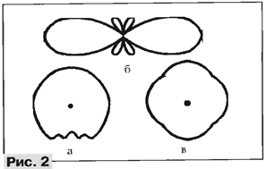
Positioning the active elements in one line, you can create a collinear antenna with increased from 6 to 12 dBd (when using from two to eight elements). The gain is achieved by narrowing NAM in the vertical plane. However when installing the antenna on a massive metal farm days will be noticeable failures in the horizontal plane (Fig. 2, a).

It is perfectly acceptable in cases where the failure falls on geographically the service territory of another repeater or the system can be designed only for priority areas (e.g. MRI Protocol-1327 or LTR). For repeater standard SmarTrunk II radial radiation is unacceptable. You can solve the problem by placing around the perimeter of the farm a few paintings vertical gratings, thereby providing a virtually circular NAM (Fig. 2, in). Small dips of course will remain due to interference effects the neighboring elements, but they will be insignificant (about 1.5...2 dB) Dips can be reduced by placing elements away from each other - on (2...3)X. In the end, you can live with - after all have to put up with fading signal 6...10 dB due to urban development!
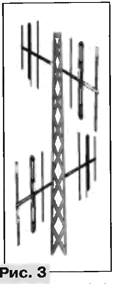
As the active elements can be used and directional antennas, for example three-element Yagi - "the wave channel". The width of the main lobe the directivity of the antenna is about 90°, this allows you to create antenna a lattice with almost a pie chart of only four paintings Yagi (Fig. 3). The gain of this antenna system will reach 5...6 dBd.

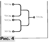
In all the cases for consolidation and phasing of the signal can to apply the adders from the coaxial cable on the basis of quarter-wave lines. All active elements are energized in parallel. This method allows save wide operating band of the antenna due to the minimum phase of the RAID which will be same in all the shoulders when the detuning relative to the Central frequency (Fig. 4).


