The article describes the developed modification of the so-called Bobtail antenna found in the American Amateur literature, for ranges of 2 m and 70 cm. the Principle of construction Bobtail shown in Fig.1.
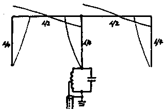
Fig.1
The antenna consists of a quarter-wave radiator and two external elements identical with the emitter length, lying in the same plane. The external elements are fed out-of-phase half-wave lines, and therefore the horizontal component of radiation is suppressed. Chart bidirectional antenna (Fig.2), with maxima of radiation in directions perpendicular to the plane of arrangement of the quarter-wave elements. The gain in the gain, compared to GP, about 5 dB.
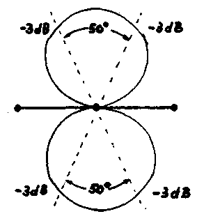
Fig.2
The author's modification of the antenna is a kind of "inverted" option Bobtail (Fig.3) direct connect 50-Ohm power cable. The exact position of the phase of the external elements in the "inverted" option is achieved by connecting the conductors are half-wave lines to the screen of the coaxial cable to the feed point.
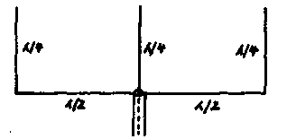
Fig.3
On the range 70 cm antenna works as 3/4l, and the extreme elements are fed 1.5 l lines. In Fig.4 shows a "wire" variant of embodiment, where AI+AI=3.04 m stranded copper wire (a=1 m, L=52 cm); with emitter length 52 cm; d - three reference PVC pipe with a diameter of 15 mm length 54 cm; e - 8 screws-screws; f - stretching of synthetic rope.
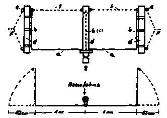
Fig.4
In Fig.5 - the "hard" option of aluminum and tubing, where a is the average plank profile 15x15 mm length 1 m; B - lateral (profile 11x11 mm length 60 cm); with three vertical radiator from the tube diameter 6 mm length 56 cm; d - BNC 50-Ohm-tion connector; e - screw cable clamp PG7; f - steel screws 3,5h13 mm for external mounting of radiators.
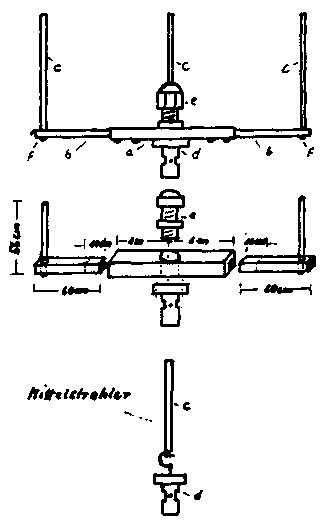
Fig.5
The following modifications Rolf suggested the use of half Bobtail antenna (Fig.6). In this case, however, the gain is 2 dB less, and the chart at 25° wider (-3 dB), but gives a very compact design.
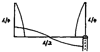
Fig.6
Adding the reflector, the construction is similar to the emitter - increasing only the length of the vertical elements by 5%, the author received a unidirectional antenna (Fig.7) with a gain of 6 dB (Fig.8).
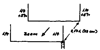
Fig.7
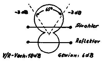
Fig.8
In Fig.9 shows the structure of the 2-element antenna, where a is a 50 Ohm BNC connector with earth petal; Ü - phasing line of insulated copper wire 1 m long with a diameter of 0.8-1 mm; with two telescopic antennas from radio receivers with threaded holes at the ends, pull to the desired length; d - PVC pipe of diameter 25 mm length 1 m; e -wooden plank HH mm with two holders for PVC pipe; f - supporting PVC pipe of diameter 25 mm, length 22 cm; d -a fitting end fixing unit.
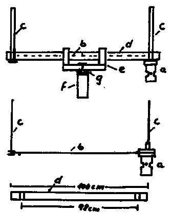
Fig.9
In Fig.10 - design of unidirectional antenna, where a, B, C, d, e, f, g - similar to Fig.79, and SG are the same telescopic antenna with both, but 5% long, h - PVC pipe of diameter 25 mm length 26 cm
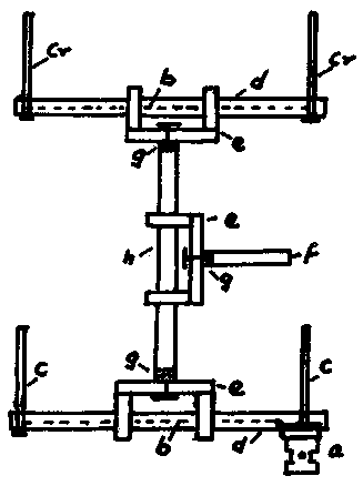
Fig.10
Literature
Publication: N. Bolshakov, rf.atnn.ru


