


")

In life, there are situations where for one reason or another speaker system connected to the audio-frequency amplifier, the power of which exceeds the maximum allowable for the system that, on the one hand, often gives the best sound quality, increase dynamic range, on the other - increases the risk of damage to the drivers due to overload.
This is especially true when using the speaker on school, student, youth parties, which often acoustics is connected to the first operational amplifier, which is "more powerful". To prevent damage to the speaker when receiving her power higher than the nominal, it is necessary to equip the node overload protection, built-in speakers and does not require an additional power supply. A schematic diagram of such a device, designed to protect AC power 10…35 W, shown in below.
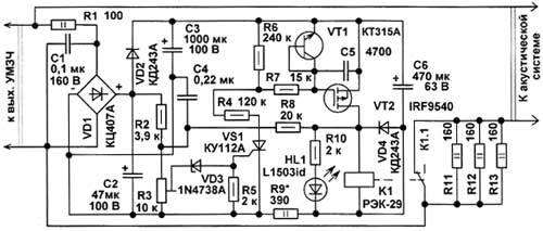
In addition to disconnecting the AC overload, this device also protects its dynamic head from damage in the event of failure of the transistors of the amplifier and appears at its output a DC voltage. The device is connected to the output of the power amplifier audio frequency. The AC voltage is rectified by a diode bridge VD1. The resistor R1 eliminates the effect of the device on the operation of the amplifier. The rectified voltage is smoothed oxide capacitors NW, S2.
While the power output of the amplifier does not exceed the maximum allowable for AC, the voltage across the terminals of the capacitor C2 is low, the Zener diode VD3 is closed, hence also closed and SCR VS1. In the regime of skin triacs are controlled, i.e. they can be closed by removing the control voltage. Since VS1 is closed, will also be closed transistor VT2. The contacts of relay K1 are closed, the dynamic head of the AU will receive 100% power.
As soon as the output power of the amplifier will exceed the AC, the voltage across C2 increases so much, that opens the Zener diode VD1, open SCR VS1 and the transistor VT2, the relay contacts K1 will open, and the amount of power going to the speakers will be limited by the resistors R11-R13. These are load resistors for the power amplifier that improves the stability of the amplifier in the event of a power speaker system, in addition, these resistors reduce arcing between the relay contacts when closing and opening.
When triggered overload protection led lights HL1. Transistor VT1, the emitter junction which operates as a Micropower voltage reference diode with voltage stabilization 7…12 V, field protects the transistor from breakdown of the gate insulator. As soon as the voltage at the output of the amplifier is reduced, the Zener diode VD3 closed closed VS1 VT2, the contacts of relay K1 closes, the speaker will again come full capacity. Resistor R8 introduces a small hysteresis, which prevents cyclic circuit-opening relay contacts at a constant power output slightly greater than the threshold. Resistor R9 reduces the current through the relay coil by opening its contacts, the capacitor C6 accumulates a sufficient amount of energy required for reliable operation of relay.
When placing structures inside the speaker design elements work in a fairly strong vibrations in a wide range of sound frequencies generated by dynamic heads, in addition, in some cases, you should consider the alternating magnetic field from dynamic drivers. The circuit Board should be placed at a maximum distance from the open magnetic systems dynamic heads.
In the device used fixed resistors MLT, Cl-4, C2-23 or imported counterparts. Trimmer resistor R3 is preferably used in an enclosed housing, for example, JS4-1, GPA-16B, SP5-16A, SDR-19a, JS4-3. After setting the rotational axis of the resistor should be fixed with a drop of paint. Capacitor C1 polyethylene terephthalate film K73-17, K73-9 or similar. C4 - ceramic K10-17, km-5, oxide capacitors C50-35 or imported counterparts. The capacitor NW can be composed of two 470 UF (provided on the circuit Board).
If necessary, the capacitor C6 should also be used at a working voltage of 100 V. if the device is used with amplifiers with voltage output stages more than ±50 V, oxide capacitors should be at a voltage of 160 V, capacity and resistance of the resistors Rl, R2, R9 also need to increase. Capacitors NW, C6 set parallel to the circuit Board and in addition fix it with a wire clamp. The diode bridge can be substituted with low-powered, for example, DB103-DB107, RB153-RB157 or make up of four rectifier diodes with a working voltage of at least 100 V. Instead KDE you can install any of the series KD, KD, KD, KD, 1N4002-1N4007.
1N4738A Zener diode can be replaced by XA, XI, XK, the led is on any other. Instead of SCR KU112A you can apply KU AM 112 in the housing-92. N-channel field effect transistor IRF9540 in this design can operate without heat sink. The maximum voltage of the source-drain 100, domestic analogue - CPA. Instead of the transistor can be used IRF9634, CPA with UCH MAX > 250 V. Instead CTA can apply any of the series CT, KT315, SS9014. Relay K1 - REC-29, passport DOES.501.56. The resistance of the winding of the relay 950 Ohm stable switch contacts occurs at a voltage of 15 V, the minimum retention voltage is 7 V. the Relay of this type were used in the modules do domestic TVs USCT. When replacing, you should consider the fact that the contacts of this relay must switch a significant current.
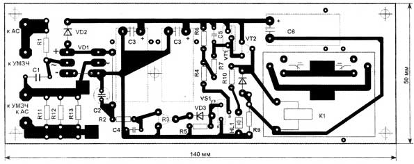
The apparatus may be mounted on the PCB size 140x50 mm, where has all the elements except the led. In Fig.2 shows the printed circuit Board from the conductors.
From the installation charge is preferably covered with three or four thin layer of epoxy glue. Each next layer is applied after curing of the previous one. Cost is attached to the body of the AU five screws from the inside of the MOH or screws. If possible it is desirable to close the deaf thick-walled (>0.5 mm) casing that will also reduce the probability of failure of the device due to vibrations in a powerful speaker, and will also reduce the likelihood of chattering of the relay contacts.
Made the author of two instances of these devices are used with acoustic system 15 ° C-220, which use dynamic heads HTN-3-4. These systems start to wheeze and rattle when the input power is more than 40 watts. The threshold is set to 25 watts. These speakers are powered from the amplifier Orbit MIND-002 stereo", which is able to develop power above 50 W at 4 Ohms. The other two instances installed in a homemade sealed AC, assembled on broadband heads DS-1, fed from amplifier "Corvette 50U-068. The threshold for inclusion of protection is also installed 25 watts of amplifier is operating at a load of 4 Ohms. If you are working with powerful AC (>35…5 ° W) and a powerful amplifier SCR will be closed at too low for the case of power, the resistance of the resistors R4 and R7 can be doubled.
This device can be modified by replacing the constant of the resistor R2, the NTC resistance 3,3…4,7 kOhm at 25 °C, through which the strip of heat conductive rubber should be rigidly fixed on the magnetic system of powerful low-frequency drivers. In this case, when strong heating of the magnetic system, the device will enable protection at a lower output power of the amplifier.
Author: A. Butov, S. CORBA Yaroslavl region; Publication: www.cxem.net