Main features are as follows: The supply voltage is 1.8 7...
Output power (each channel), MLT 15... 30
The quiescent current, mA 20 14...
Harmonic distortion pre-amp, % 0,25 0,05...
The harmonic distortion of the output stage, % 0,2... 1
Maximum attenuation of the volume control, DB 66 75...
The parameters have to say, not very bad, and indeed what they should be, if you want mobility!
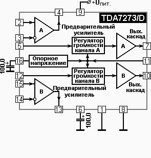
Block diagram of the amplifier:

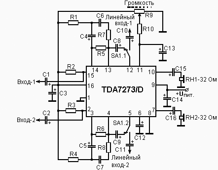
Strictly speaking, this scheme is caught in the repair of one of the old, but good quality players. And here is the booster circuit:

And as expected, the sign elements:
Element
The value
Note
R1, R4
220 Ohms
0,125 W (or SMD 0805, 1206)
R2, R3
2.2 kω
-//-
R5, R6
82 kOhm
-//-
R7, R8, R10
6,8 kOhm
-//-
R9
47 kOhm
Logarithmic
C1, C2
Thu
Any electrolytic
C3, C12, C14
Thu
-//-
C4, C5
Thu
-//-
C6... C11, C13
Thu
-//-
C15, C16
Cf,3B
-//-
In establishing the scheme does not need, the only problem was associated with self-excitation of the amplifier, but it was immediately resolved to increase the capacity of the electrolytic capacitor C14 to 470 UF.
And in conclusion - if you want the input to pre-amp to connect the magnetic pickup, the capacitors C1, C2 are excluded from the scheme, and the pickups are connected in series with resistors R2, R3, relative to the common conductor.


