


")

Schematic diagram of the receiver pulsed infrared signals shown in Fig. 35. The output can be connected to the input digital CMOS circuits directly. If the head needs to be removed from a digital analyzer, and the capacity of the connecting cable will exceed 100…200 pF, photoshelter will need to be supplemented buffer amplifier. Therefore, for example, as in Fig. 36, and (amplifier-inverter) or in Fig. 36, b. Capacitive load the photo-head with such an amplifier at the output can be increased to 0.01 UF.
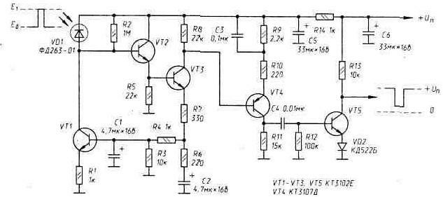
Fig. 35. IR the receiver transistors
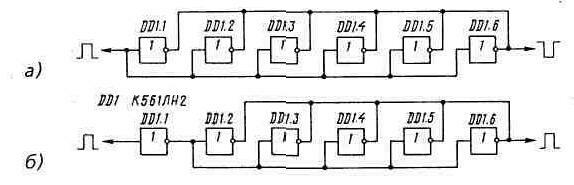
Fig. 36. Amplifiers power in CMOS technology
Table 7
U N And M,B
Potr,mA
4,5
0,30
5,0
0,30
6,0
0,32
7,0
0,34
8,0
0,35
9,0
0,37
Photodiode FD-01 can replace FD. And with a good optical concentrator is almost to any of those specified in Appendix 2.
IR receiver keeps working when the voltage of the power source u pit in a wide range. The dependence of the consumed current Potr from the supply voltage shown in table 7.
Publication: www.cxem.net