High requirements to modern speakers, can only be met by using multiple loudspeaker systems with two, three or more dynamic heads, each of which plays only the relevant part of the spectrum supplied to the loudspeaker of the wideband signal. Depending on the number of bands playing acoustic systems can be two-, three-way, etc are the Most common in Amateur practice received two - and three-way speaker system. Acoustic system with a large number of bands used by the professionals.
An integral part of any multiple loudspeaker systems are the separation filters which provide a summary for each dynamic head only those frequencies of the signal to play which it is intended. Total the number of filters equal to the number of heads. Depending on the frequency bands for playback which is the head, there are low-, medium - and high-frequency dynamic heads. Recommended values of boundary frequencies the separation filter 500 Hz, 1, 2, 3, 4, 8 kHz.
The choice of the boundary values of the frequency separation of the strips depends on the frequency properties of dynamic drivers and values of their rated power. In Fig. 1 shows the curves of the capacity of low-, medium - and high-frequency heads depending on the cutoff frequency separation of the strips relative to the power head broadband, capable of reproducing power is equal to output power, ULF, to work together with which is designed multiband sound system. The dashed line shows the high-frequency power heads three-way systems.
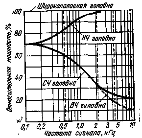
Fig.1
As can be seen from Fig. 1, at high frequency the boundaries of separate lanes (2 to 4 kHz) power head low frequency should be equal to the power of broadband heads, whereas the high-frequency power head two-tiered system and mid-range three-way systems can be from 25% to 15%. At low engine power section heads low and medium frequency (or high) should be respectively 82 and 60% of the power head broadband.
Theoretically, in relation to a standard audio programs, power heads, medium and high frequency could be reduced by 1.5-2 times compared with the data of Fig. 1. But this should not be done, since it is necessary to have a supply rated power heads that work with ULF overload or excitation. If this is not done, it is possible to output high - and midrange down.
Two-way crossover networks
In Fig. 2 shows schematic diagrams of the most simple dividing single-link and two-link (b) filters, and given their amplitude-frequency response at boontanon frequency change signal (in). Simple filters contain one capacitor and the inductor, providing a slope of attenuation at the crossover frequency of 6 dB/octave, i.e. with each increase in the frequency of the signal by half relative to the frequency separation occurs attenuation of 6 dB (4 times the power).
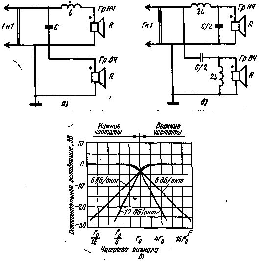
Fig.2
Two-tier filters contain two capacitors and two inductors of various denominations, as proven in Fig. 2,b. They are more complex simple, but provides twice the slope of the characteristic attenuation at the crossover frequency of -12 dB/Oct. The difference of the characteristics of these filters is shown in Fig. 2,V.
Depending on the nominal resistance value drivers in R, the frequency separation of the strips F the capacitance C and the inductance of the coil L can be determined from the known formulas:

where C is the capacitance of the capacitor, f; L is the coil inductance, GN, F is the frequency separation of the bands, Hz; R is the resistance of the voice coil head, Ohm.
When calculating the parameters of the simple elements of the separation filter according to the scheme of Fig. 2,and is convenient to use the data of the nomogram, shown in Fig.3 a,which shows the dependence of the inductance coils and capacitors of the frequency division bands and resistance of the voice coils of the speaker units (4 and 16 Ohms). If you know the dimensions of the coil form and the amount of winding, number of turns can be calculated by the formula, which takes into account the dimensions specified in Fig. 3,b:

where n is the number of winding turns; Z-coil inductance, GN, d is the average diameter of the coil, cm; b-width of the winding, cm; C-average thickness of the winding, see
Data of Fig. 3,a and b can be used in the calculation of the separation filters with two links (see Fig. 2,b). In this case, the capacitance decreases and the inductance is increased by 2 times, which will privada to increase the number of winding turns in 1.4 times.
In the manufacture of the elements of the separation filters should be kept in mind. The capacitors must be non-polar, i.e. electroless. It can be paper, metal, paper or ceramic capacitors. If there is no capacitor required capacitance, it can be made up of several smaller capacitors, picking up their number so that the total capacity was equal to the desired value. It is recommended to use capacitors having the dispersion capacity of not more than ±10% from the nominal value.
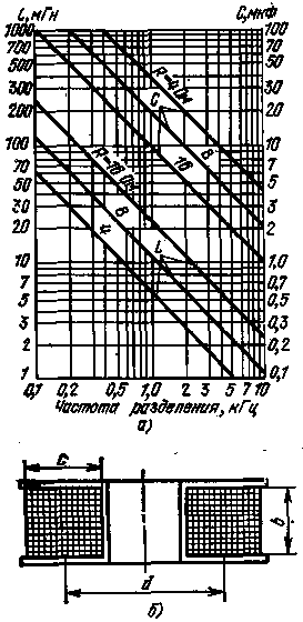
Fig.3
Wound inductors should be possible with a thicker wire brand sew-2 to active power loss of the signal in the separating filters were minimal. On average, the winding is carried out with a wire diameter of 0.5 to 1 mm, and more than input power, the thicker must be the wire. This is a great disadvantage of multiple loudspeaker systems - in cumbersome separation filters is lost from 10 to 25% of the power input to the speaker. In this regard, electro-acoustic systems with multi-band ULF clear advantage.
Dual band filter for single head...
Let the reader does not think that a typographical error. Everything is correct. We are talking about an adjustable filter, designed to accentuate the lower and upper frequencies in the speaker, contains only one dynamic head.
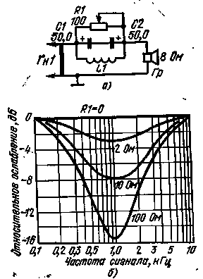
Fig.4
Its schematic diagram is shown in Fig. 4,and the amplitude-frequency characteristic in Fig. 4,b. With the help of variable resistor R1 can be adjusted attenuation of an average frequency of about 1 kgcd level -16 dB relative frequencies of 0.1 and 10 kHz. The principle of operation is based on the use of a serial resonant circuit consisting of inductor L1 1 mH and two series-connected electrolytic capacitors C1 and C2 50 UF each. Counter enable condensers are used .use two electrolytic capacitor as one non-polar. Variable resistor shunt resonant circuit, thereby affecting the amplitude-frequency characteristic of the filter as a whole.
Adjustable filter connected between the loudspeaker with a single head broadband Gr impedance of 8 Ohms and ULF, helps to significantly improve the sound quality of the loudspeaker when operating with a low level of input power. The filter would take into account the physiological feature of the human ear to reduce its sensitivity to the upper and lower frequencies compared with the average decreasing audio volume. Obviously, the filter according to the scheme of Fig. 4,and is most suitable for simple electroacoustic devices that do not have effective adjustments loudness and timbre.
A three-color separation filters
Schematic diagram of the simplest three-way two-link separation filter and its frequency response are shown in Fig. 5,a and b. Crossover frequencies are respectively 750 Hz (between the bottom and middle) and 7 kHz(between middle and upper). The steepness of the recessions of the amplitude-frequency characteristics outside the pass bands-12dB/Oct. Depending on the choice of the capacitors and inductances of the coils of the filter can work with low-, medium - and high-frequency heads, with the resistance of the voice coils 4, 8 and 16 Ohms. Thus in one unit can be used head only with the same resistance.
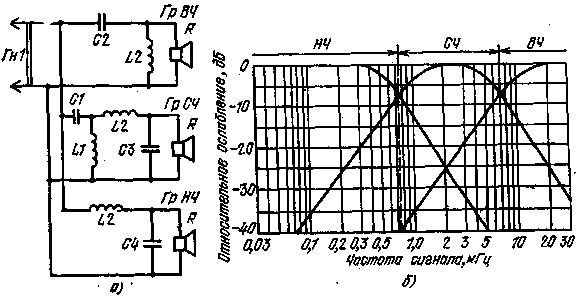
Fig.5
In the manufacture of three-band dividing filter according to the scheme of Fig. 5,and the inductors and capacitors take from the table. 1. Selecting capacitors and manufacturing coils should follow the recommendations given in the description of the two-lane separation filters and also to use the nomogram and the drawing, is shown in Fig. 3,a and b.
As shows Amateur radio practice, the use of two - and three-way speaker systems, equipped with simple separation filters, greatly improves the sound quality compared to the speakers using only one broadband head. At the same time, most use of multiband systems requires special acoustic design of heads and correction of their characteristics.
Table 1
Filter elements
The nominal value of the filter elements
R, Ohm
4
8
16
C1, UF
40,0
20,0
10,0
C2, IFF
4,0
2,0
1.0
L1, mH
1,25
2,5
5,0
L2 GN
0,125
0,25
0,5
Literature
Publication: N. Bolshakov, rf.atnn.ru


