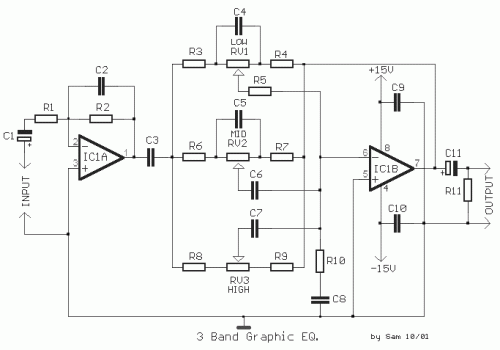
A classic circuit of regulation of tone of three way, with which we can regulate low, mid and high frequencies, of acoustic signal. The boost/cut can be regulated in the range of ± 18 dB/oct. In the circuit the supply is ± 15V, but can be also supplied with alone supply + 9 until + 30V, it is enough it is connected pin the 4 IC1, in the 0V and is connected the circuit with as it appears in fig. 2, giving half the supply in the not inverting entry of IC1, in the 5 and 3 equivalents, which are henceforth not connected in the ground.
Circuit diagram Part list
- R1-2= 47Kohms
- R3-4-5-12-13= 10Kohms
- R6-7= 3.3Kohms
- R8-9= 1.8Kohms
- R10= 270ohms
- R11= 22Kohms
- C1-11= 10uF 25V
- C2= 33pF ceramic
- C3= 2.2uF 63V MKT
- C4= 47nF 63V MKT
- C5-7= 4.7nF 63V MKT
- C6= 22nF 63V MKT
- C8= 1.2nF 63V MKT
- C9-10= 100nF 63V MKT
- C12=47uF 25V
- RV1-2= 100Kohms Lin.
- RV3= 470Kohms Lin.
- IC1= TL072, NE5532


