


")

Specifications:
- Signal to noise ratio: -100dB with respect to 1V output, 4.7kW input load.
- Frequency response: -3dB at 2Hz and 200kHz.
- Total harmonic distortion: less than .001% from 20Hz to 20kHz with a 1V input.
- Signal handling: supply dependent; requires 30VDC or ±15V for 9V RMS signal handling.
The reason professional audio equipment utilises balanced inputs and outputs is quite simple. It’s done so that audio connections can be made over quite long distances without adding extra noise to the signal. These balanced connections use 3-pin XLR plugs and sockets and screened twin-core cable.
Block diagram:
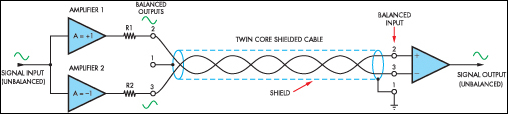
Block diagram shows the basic arrangement. Basically, the audio output signal is coupled to two separate amplifiers and these drive the two signal leads in the cable in anti-phase (ie, the signals have opposite phases). In this case, Amplifier 1 has an output signal that’s in phase with the input, while Amplifier 2 has an output that’s opposite in phase with the input.
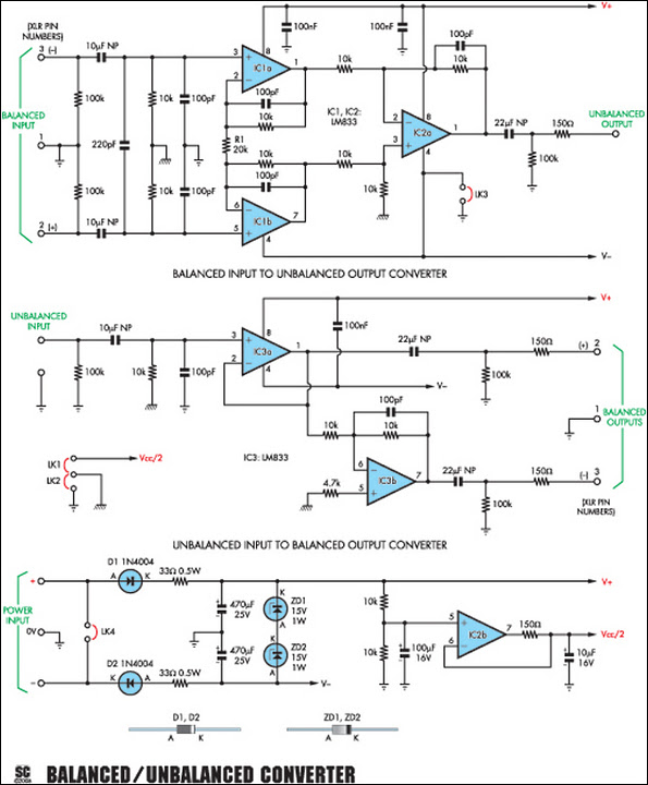
Circuit looks like:
The output impedance of each amplifier is the same and the twin-core cable carries the signal to the equipment at the other end. However, in some cheaper balanced line drivers, one core does not carry any signal but is grounded instead. So in this case, Amplifier 2 is left out and the left hand side of resistor R2 is grounded.
In operation, there will be some noise and hum pickup over the length of the cable even though the cable is shielded. However, because the cores in the cable are close together, any signal that is picked up will be common to both.
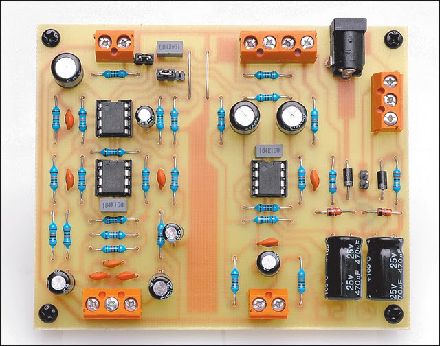
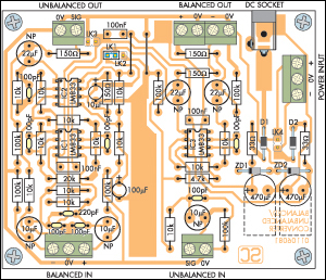
Parts layout:
At the receiving end, the signal in each of the two cores is subtracted to produce the original audio signal. At the same time, this also removes most of the noise and hum that was picked up in the leads, since the same noise signal is present in both.
Circuit diagram:
If one of the cores is grounded, as in the cheaper type of balanced driver, then the signal level after subtraction will be the same as the signal in the main core. Alternatively, if anti-phase signals are applied to both cores, the subtraction process produces an audio signal level that’s twice the level in the individual cores.
Source: Silicon Chip 09 June 2008