Quite often in Amateur practice the need arises adjustment of the AC voltage in the range 0...220 V. Widely used for this purpose Lattre (autotransformers). But a century has passed and at the same time bulky handsets came modern thyristors, which have one drawback: the pressure in such devices is regulated by changing the duration of the pulses of the AC voltage. Because of this, it is impossible to connect highly inductive load (such as a transformer or inductor, and also any other radio device, comprising the above elements).
From this lack of free this regulator AC voltage. He combines: device overload protection, thyristor controller voltage with a bridge controller, high efficiency (92...98%). In addition, the regulator works in conjunction with a powerful transformer and rectifier, which can be used to charge car batteries and as a starting device during a low AB.
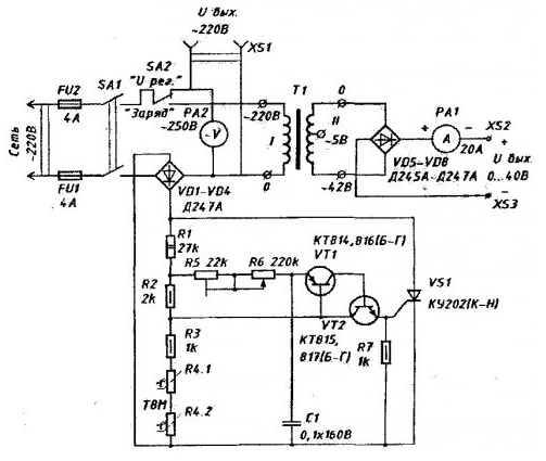
The circuit of the voltage regulator:

The main parameters of the voltage regulator:
- Nominal voltage, V 220 ± 10%;
- Output voltage AC 0...215;
- Efficiency, not less than, % 92;
- The maximum power load, 2 kW.
- The main parameters of the charging-starting devices:
- Output voltage, V, DC 0...40;
- DC current consumed by the load, And 0...20;
- Inrush current (start 10 c), A 100.
Description voltage regulator
The switch SA2 is selected or adjustment of the AC voltage within 0...98% of the network, which is removed from the nests XS1, or constant adjustment voltage in the range 0.. .40 At the output terminals XS2 and XS3.
The average or effective value of the voltage is regulated by changing the phase firing angle of the power thyristor. Introducing a delay in the opening thyristor key, we thus change the value of the average current flowing through the load.
The elements VT1 and VT2 completed an analog unijunction transistor, Manager the performance of the power thyristor VS1. The locking voltage is supplied to the base transistor VT1 from the voltage divider formed by the elements R1...R4. Elements R5, R6 and C1 form a phase-shifting circuit. Changing the resistance resistor R6 is possible to change the charging time of the capacitor C1 to the value of the locking voltage, and thereby adjust the delay time of the thyristor VS1. So is the power regulation in the load. The resistance of the resistor R5 sets the upper value of the output voltage. It should be borne in mind that, increasing the resistance of the resistor R5, we reduce the output voltage. When the decrease in the resistance of the upper threshold voltage will first increase, and then begin to decrease. The resistance of the resistor must be chosen so that if the voltage is maximized.
Protection from current overload when you turn on the AC voltage regulator in the network is provided by the inclusion in the circuit of resistors R4.1 and R4.2 having a negative TCR. Due to the thermal inertia of the thermistor threshold locking the voltage supplied to the base of VT1, has a maximum value at the time turn on control and gradually decreases as the heating of the thermistor the current flowing through the voltage divider. Accordingly, the output voltage in the first moment after the inclusion of marginal value and gradually increases in over a period of time defined by the thermal inertia of the thermistor (approximately 1...2), seeking to set value. While the load and the power components are reliably protected against over-current during startup.
Interchangeability of parts voltage regulator
Instead of thermistors TN in the voltage regulator can be supplied by any thermistors series T8 and T9 (in this case, the time mode will be somewhat to vary).
The switches SA1 and SA2, as well as all of the mounting of the high-voltage wire the device must be rated for a current of 5... 12 A. All radioelements, subjected to thermal overloads, must be mounted on heat sinks the corresponding surface area; VS1 - at least 250 cm2; VD1...VD8 - not less than 150 cm2 on each of the diodes; VT1 and VT2 - at least 10...15 cm2 each the transistor.
If the device is used not only for charging, AUTO-AB, but to start the engine, it is necessary to consider the following:
1. Diodes VD5...VD8 should be used for a current of less than 80 A and Iobr. not less than 100 In (for example, D-80S) and install them on the appropriate tapoatafa square (not less than 300 cm2 on each of the diodes).
2. The wires connecting the low-voltage part of the device should be designed on short-time current 100...150 A, i.e. to have the cross-sectional area not less than 35 mm2, they must be as short as possible.
3. Ammeter RA1 must be rated for a current of less than 100 A. the Ammeter to the current 20 And it is better to turn off (short circuit) or even to abandon it.
Literature
Author: A. Filipovic, Dzerzhinsk


