The article describes the console is designed to work with charger device from which the function disconnect from the mains when charging rechargeable batteries. This attachment should be of interest in the first place, those motorists who had the simplest charger factory manufacture or improvised, like with a minimum of time and tools to automate the charging process.
It is known that the voltage across the terminals of the charged stable current acid-lead batteries almost stops increasing, as only she will get a full charge. From this moment almost all incoming the battery energy is only spent on electrolysis and heating of the electrolyte. So by the way, at the time of termination of increasing the charging voltage could disconnect the charger from the mains. Instruction manual car batteries [1] recommends, however, continue to charge the battery in such mode for two hours. This is how automatic charger, I have described previously [2]. However, practice shows that this recharging really only necessary when conducting annual control and prevention saragnayan cycle to determine the technical condition of the battery.
In everyday life is enough to withstand the battery under constant voltage (15...30 min This approach simplify automatic charger without noticeable the impact on full charge the battery. If you charge the battery unstabilized current, together with a gradual increase of charging voltage (pronounced weaker, than in the first case) there is a reduction of the charging current. The full testimony of charge of the battery is the termination of change of the voltage and current.
This principle is the basis of the proposed prefixes. It contains a comparator, one input of which a voltage proportional to increasing with increasing charging voltage on the battery (and decreasing when you decrease) proportionally and simultaneously reduced with the increase (increasing with decreasing) the charging current. To the second input filed the same the voltage on the first, but with a significant time delay. In other words, will increase until the voltage on the battery and (or) decrease the charging current, the voltage value at the second input of the comparator will be less the voltage values at the first, and this difference is proportional to the rate of change charging voltage and current. When the voltage on the battery and the charging current stabilize (which would indicate full charge of the battery), voltages at the inputs of the comparator will be equal, it will switch and will give the signal to stop the charger. This idea is borrowed from [3].
The console is made on the common elements. Maximum operating the current is 6 A, however if necessary it can easily increase.
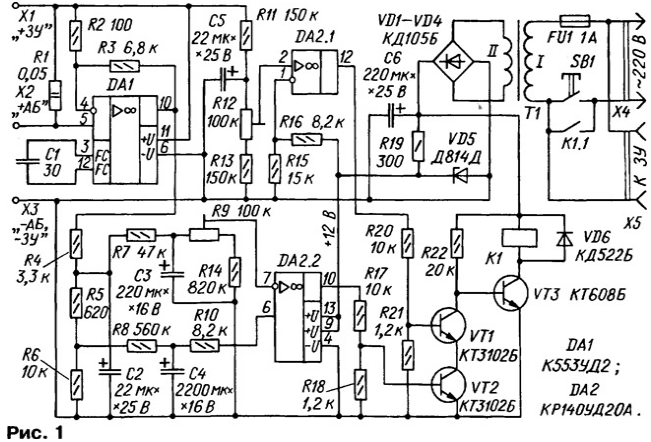
Schematic diagram of the console shown in Fig. 1.

The device consists of input opamp DA1, two voltage Comparators at the shelter DA2.1, DA2.2, dlouhodobeho electronic relay VT1 - VT3, K1 and power unit, consisting of a network transformer T1, diodes VD1-VD4, the smoothing capacitor C6 and parametric voltage regulator VD5R19. Charger output connected to the terminals X1, X3, and a rechargeable battery to the terminals x2, X3. Network plug the charger connected to an outlet X5 consoles.
When you press the SB1 voltage supplied to the charger and network winding I of the transformer T1 consoles. Unstabilized voltage with diode bridge VD1-VD4 is powered electronic relay, and an output voltage parametric stabilizer - chip DA2 (DA1 charger is powered by the device). Begins charging the battery.
The voltage drop generated by the charging current on the resistor R1 is input to Oh DA1 connected in the circuit of an inverting amplifier. The voltage at the output while reducing the charging current will increase. On the other hand, the output voltage OU proportional to its supply voltage. And since the amplifier powered directly with a rechargeable battery, the output voltage of the shelter will be function as the voltage at the terminals of a rechargeable battery and the charging current. Such the build console gave me an opportunity to use it in conjunction with a variety of chargers, including protozoa.
The output of op-amp connected LPF R4C2, with which the voltage across the integrating circuit R7C3 and R5R6R8C4 arrives at the inputs of the comparator, performed at the OS DA2.2. Chain R8C4 has a time constant that is many times greater than the chain R7C3, so the voltage at the noninverting input of the comparator would be less than inverting, and the output will be set low.
The comparator at the shelter DA2.1 is a conventional threshold device, inverting input of which is filed exemplary voltage with resistor divider R15R16, and the non-inverting - divider R11R12R13 connected to a rechargeable the battery pack. The comparator switches when the battery voltage 14.4 V and serves to prevent premature disconnected the charger in the context of low dynamics of change the battery voltage.
As a result, while the voltage of a rechargeable battery reaches a specified value, the console will shut off the charger, even if switched the comparator DA2.2. Such situation is possible when installing low values charging current and, as a result, when changes are very slow charging voltage and current. Initially, the output of the comparator DA2.1 also acts the low voltage level.
The outputs of both Comparators using resistive dividers R17R18 and connected to R20R21 bases of transistors VT2 and VT1. Thus, when you press the SB1 these the transistors remain closed, a VT3 opens. Relay K1 and the contacts K1.1 blocks the contact of a button. The console stays on after releasing the button.
Since the transistors VT1 and VT2 are included in a logical way And they open only at a high voltage level simultaneously at the output of the Comparators DA2.1, DA2.2. This can only happen when the battery is fully charged. In this case, the transistor VT3 is closed and the relay K1 releases the armature, opening the circuit power consoles and charger.
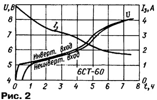
In Fig. 2 shows graphs of voltage at the inputs of the comparator DA2.2, and also the charging current during precharge the battery 6ST-60 through a simple charger with unregulated charging current. The initial charge level of the battery is about 75 %.

In the case where the console will work in conditions of strong interference, the power circuit Oh DA2 should be bypassed with a ceramic capacitor of 0.1 μf.
The prefix is distinguished by its low sensitivity to voltage variations. If, for example, increases, increases and the voltage on the charged battery, but at the same time will increase the charging current. As a result, the voltage at the output of op-amp DA1 will change slightly.
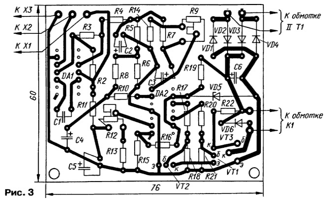
The console is mounted in a metal box the size of 140x100x70 At its mm. the front panel hosts the terminals X1-X3, the fuse FU1 and socket X5. Big some details consoles placed on the PCB size 76x60 mm, made of foil fiberglass 1.5 mm thick. a Drawing Board is depicted in Fig. 3. The transformer T1 and the relay K1 is mounted separately near Board. The R1 resistor is soldered directly to the terminals X1, x2.

The resistor R1 is composed of two parallel connected resistors C5-16V resistance of 0.1 Ohms and a nominal power dissipation 1 W; the other constant - MLT. Trimmer resistors R9, R12 - SDR-16V.
Capacitor C1 - KM5, the rest - C50-35. The capacitor C4 is desirable before the installation cost for exposing, connecting it for a few hours to DC power supply 10...12 V.
Instead KD105B you can use diodes KDA, and instead CDB - any of a series KD521. The Zener diode VD5 - any low-voltage stabilization 11... 13 V.
Transistors CTB interchangeable with any low-power appropriate structure with static current transfer ratio base not less than 50, and when replacing transistor VT3 should focus on the current response of the existing relay K1. When selecting a replacement OS CUD be aware that not all operating amplifiers allow operation with an input voltage equal to supply.
The device uses ready low-power mains transformer with a variable a secondary winding voltage of 14 V At a load current of 120 mA. Relay K1 - RMU, passport RS4.523.303, but with any voltage 12...14 V the contacts are designed for switching AC voltage of 220 V at a current 0,3...0,5 A.
To establish consoles will require a stable voltage source, adjustable in the range of 10... 15 V, and a digital voltmeter with a limit of measurement 20 V. First engine of the resistor R12 is set in the bottom, a R9 - in on the left the diagram position. To the terminals X1 and X3 connects source, mounted on his the output voltage of 14.4 V and include the prefix in the network.
Click on the button SB1, this should work the relay K1. Make sure that the outputs OU DA2.1 and DA2.2 (pins 10 and 12) there is a low level voltage (1,3 1,5...). Then measure the voltage at the output of op-amp DA1 (pin 10). It should be approximately equal to the voltage of the connected power source.
Close to 30.. .40 with the findings of the resistor R8, providing fast charging capacitor C4, and then after a ten-minute exposure voltmeter connected to the output of op-amp DA2.2 and smoothly rotate the handle of the resistor R9 to the moment of switching of the comparator, i.e. abrupt increase in the voltage at its output up to 11... 11,5 V. Then measure the voltage at the inverting input of op-amp DA2.2 and resistor R9 reduce it to 15...20 mV.
It should be noted that to measure the voltage in the input of the comparator circuits need digital voltmeter with an input resistance of at least 5...10 Mω to not to prevent discharge of the capacitor C3. Since the input impedance of many popular digital avometr does not exceed 1 MW, you can enable the input available voltmeter desyatiyurodnye resistor, forming together with the input the resistance of the device a voltage divider with a ratio of 1:10.
In conclusion, rotate the handle of the resistor R12 to the moment of switching the OS DA2.1. When this relay K1 must release the anchor.
If the radio is missing the digital voltmeter and there is no power source, to establish a console directly in the actual process of charging the battery. To do this, connect to the console charger and battery, switch the charger is set to the "on" position and the engine resistors R9, R12 consoles - as above. Click on the button SB1, make sure that the relays K1 and set the charging current in accordance with the instruction manual of the battery charger.
Further monitors the charging process, periodically measuring the voltage across the terminals. When it reaches 14.4 V, rotate the handle of the resistor R12 till the moment of switching the OS DA2.1.
When the voltage ceases to increase, continue charging in this mode even 20...30 min and then slowly rotate the handle of the resistor R9 to the actuation Oh DA2.2 and turn off the console and charger from the mains. The establishment of done.
In conclusion, it should be noted that to ensure complete charging of the battery battery, it is desirable to set the maximum allowable value of the charging current in order to ensure a good momentum of change of voltage at the output of op-amp DA1. This is especially true chargers with unregulated output current and deeply discharged batteries.
Literature
Author: K. Kupriyanov, St. Petersburg


